
While there is no doubt that Felix Wankel’s rotary engine was a good idea at the time, the execution of the idea was, and remains problematic in terms of the considerable engineering challenges that have yet to be resolved in order to make rotary engines a reliable, fuel efficient, and clean alternative to conventional reciprocating internal combustion engines. Despite its many advantages over conventional engines, the rotary engine was as much killed off by the inherent defects in its design, as it was by failing to meet the demands of the Euro 5 emissions regulations. In this article, we will take a closer look at what rotary engines are, how they work, and the design/reliability issues that eventually caused its demise, starting with this question-
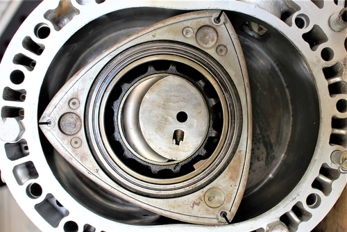
The image above shows a close-up view of one rotor inside the engine casing, which has what is called an epitrochoid shape. Note the bulges at the midpoints of the oval’s long axes; the amount by which these bulges extend into the engine casing is equal to the offset on the eccentric shaft that serves as a rotary engines’ crankshaft.
It should be noted that the rotor does not rotate in the engine casing, but orbits around a gear (not shown here) that is fixed to the engine casing. In practice, gear teeth (not shown here) in the rotor mesh with the fixed gear, and rotary motion is imparted to the eccentric shaft that serves as a sort of crankshaft when the rotor orbits the fixed gear, hence the bulges in the oval engine casing.
As a practical matter, the bulges in the shape of the casing serve to create three chambers that rotate long with the rotor: the first being a combined inlet/compression chamber, the second being a combustion chamber, and the last being a chamber that contains the exhaust gas. Fixed ports in the engine casing allow the intake charge to enter the engine, and the exhaust gas to exit the engine. In the image above, the inlet port can be seen just to the right of the upper apex of the rotor.
In terms of its operation, the intake air is compressed in a decreasing volume (seen here to the bottom left of the engine casing) as the rotor orbits the fixed gear. As the rotation continues, the apex that separates the intake chamber from the combustion chamber passes two spark plugs that ignite the air fuel mixture, and the resulting combustion pressure forces the rotor to swing around the fixed gear. The trailing apex in the combustion chamber sweeps the exhaust gas around the engine casing, and expels the gas when the volume between the rotor and the engine casing deceases toward the exhaust port.
This process has been described as being analogous to a single cylinder three-stroke engine, and while the analogy is not perfect, the way rotary engines work produces extraordinary amounts of power from relative small displacements, albeit at low torque values due to the short “strokes” of these engines, which made rotary engines unsuitable for applications where useable torque was required at low engine speeds.
The rotary engine was not killed off by a single problem. It was killed off by several interconnected issues that have so far been impossible to resolve satisfactorily, although some improvements to both the basic design of the rotary engine, as well as fuel management and ignition control have reduced their overall effects somewhat. Nonetheless, the basic issues remain, and while this article cannot delve into the physics of these issues, it can provide an overview of the problems that killed off the rotary engine, starting with-
Poor thermal efficiency
Unlike reciprocating engines that have highly engineered combustion chambers, the combustion chambers of rotary engines are long, narrow, and move along with the rotor as it rotates, none of which is conducive to effective combustion. Moreover, in a rotary engine, the detonation flame propagates in the direction of the rotors’ movement, which has a significant quenching effect on the detonation flame, thus reducing thermal efficiency further because a significant percentage of the air/fuel mixture remains uncombusted.
In practice, the propagation of the detonation flame exerts a slight braking force on the rotor, and to counteract this, engineers introduced a pronounced indentation in the rotor to “constrain” the detention flame. While this did improve combustion somewhat, it could not prevent the combustion chambers’ trailing edge from forming a so-called “squeeze stream” that prevents the detonation flame from reaching the trailing apex of the combustion chamber.
The practical effects of poor combustion and low thermal efficiency are that at low engine speeds a rotary engine cannot develop much torque, since the “levering action” that powers a reciprocating engine is largely absent. In fact, much of a rotary engine’s power at high engine speeds derives purely from the kinetic energy that is stored in the rapidly rotating rotors, unlike reciprocating engines where torque is mainly the result of the relationship between the diameter of the cylinder bore and the length of the stroke.
Poor rotor sealing
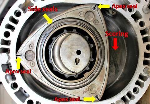
The image above shows some detail of the main sealing points on rotors. Note the slits at the apices marked with yellow arrows; these are the points where the apex seals fit into the rotor, and where the loads on seals are the greatest. In practice though, apex seals are small metal strips that perform the same function as piston rings, but because apex seals are very narrow, their effective sealing surfaces are also very small. Although apex seals sit on spring loaded “supports”, they are in large part held against the inner surface of the engine casing by centrifugal force, which obviously changes as the engine speed changes. However, and apart from the centrifugal force component, sealing is also aided by gas pressure and a film of lubricating oil that is injected into the engine casing from a separate reservoir by a dedicated oil pump, and it this mechanism that caused the most issues.
As we know, heat is the single biggest factor that degrades engine oil, and in the case of rotary engines, some of the apex seals’ lubricating oil comes into direct contact with the detonation flame, which carbonises some of the oil. As the rotor rotates, most of the degraded oil and carbon is swept up and expelled through the exhaust port, but some remains, which has a devastating abrasive effect on all the apex seals as they sweep the carbon around the inside of the engine casing. Consider the image below-
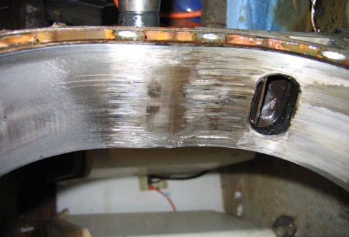
This image clearly shows the infamous “devil’s claw marks”, which are deep score marks in the engine casing that occur when the film of lubricating oil breaks down, or when carbon granules are caught up between the apex seals and the engine casing. In this condition, the combustion pressure cannot be contained, which further reduces the already-poor thermal efficiency of the engine. In fact, “devil’s claw marks” is the most common failure mode on rotary engines, and at least 80% of rebuilds at relatively low mileages were required because of it.
High emissions
There were two primary reasons why emissions from rotary engines could not be controlled effectively. The first is the fact that apex seals required large amounts of oil for lubrication, some of which was combusted, while the rest was expelled through the exhaust. The second reason involves the fact that unlike reciprocating engines, there was always fuel present on both sides of at least two apex seals.
Given the nature of apex seals, it is inevitable that both fuel and oil would seep past them, with excessively high levels of uncombusted hydrocarbons being the result. In fact, despite significant improvements in rotor sealing in general the last iteration of the rotary engine, which incidentally, no longer suffered from differential expansion, failed to meet the Euro 5 emissions standard. As a practical matter, this meant that no vehicles with rotary engines could be offered for sale in Europe after 2010/11, which was the single most effective nail in the rotary engine’s proverbial coffin.
Poor fuel economy
The combination of poor rotor sealing, low thermal efficiency due to the shape of the combustion chamber, and low mean effective pressures at light engine loads required extremely rich air/fuel mixtures just to keep a rotary engine turning over at low engine speeds. In fact, a typical naturally aspirated 13B rotary engine required fuel mixtures as rich as ten parts of air to one part of fuel, which resulted in fuel consumption that compares with that of late model V8 engines found in Ford Mustangs, Chevy Camaros, Dodge Chargers, and the like.
Although later iterations of the rotary engine used improved spark and fuel delivery strategies, most rotaries still required such rich mixtures that the exhaust emission treatments that were available as recently as 2010 could not cope with the excessively high hydrocarbon loads in rotary engines’ exhaust streams.
However, it must be stated that if a rotary engine is operated at constant speeds and loads, its fuel consumption drops to that of a modern reciprocating engine with a comparable displacement.
Consumer resistance
Although rotary engine technology will always have die-hard fans, the vast majority of car buyers/owners were deterred by the inherent reliability issues that came with the technology. One of the major issues was the unreliability of the oil injection system, which if it worked, required constant topping off to prevent engine damage.
For reasons that are not entirely clear (even today), Mazda was never able to resolve the problems in the oil injection system, and somewhat disingenuously, Mazda even recommended that users pre-mix fuel and oil to ensure proper lubrication of the apex seals, which was too much to ask of the average car owner. Normal, reciprocating engines just did not have these kinds of issues, with the result that even as early as 2004, sales of rotary engine equipped vehicles had fallen off to the point where these vehicles were produced and sold at loss to the manufacturer.
With the clarity that perfect hindsight brings, it is easy to see why rotary engine technology could not survive in the face of rapidly improving reciprocating engines. Nonetheless, official Mazda sources have confirmed that development of rotary engine technology has been resumed. Although no further details are available, there is some evidence to suggest that Mazda is developing a rotary engine for use in electric vehicles as a “range extender” to improve the limited range of these vehicles.
Whether or not the expected iteration of rotary engine technology will suffer from the same defects/deficiencies as previous versions remains to be seen, but since official Mazda sources did mention that their engineers are working on developing vastly improved exhaust treatments, it seems likely that high fuel consumption and excessive emissions will also characterise the “range extending” rotaries.
