Given the fact that valves and valve seat inserts operate at temperatures of up to 600 degrees Celsius in a highly corrosive environment without any lubrication present, have you ever wondered why the contact surfaces on valves and valve seat inserts don’t wear away within a few thousand kilometres?
Moreover, since valves and valve seats essentially operate under boundary lubrication conditions, common sense would dictate that the complete lack of lubrication in the contact interface would make it impossible for the valves in most engines to outlive the engines they are fitted to.
Therefore, if valves do not wear away despite a lack of lubrication, there must be another mechanism that protects valves and valve seat inserts against extreme mechanical wear in the vast majority of engines in use today. It turns out that there is indeed such a mechanism, and in this article, we will take a closer look at this mechanism in terms of what it is, how it works, and why it sometimes fails. Let us start with describing some of the-
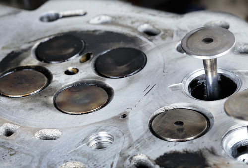
This image shows the effects of all the forces that act on an average engine valve. In this example, which is a compound valve, the valve stem snapped off at the junction between the soft, sodium-filled stem and the hardened head, and the seat shows evidence of pitting, which is the precursor condition that leads to serious burning and leakage. In addition, the valve’s sealing surface shows some evidence of excessive wear and recession, which is typically the result and/or function of excessive relative motion between the sealing surfaces.
As a practical matter, it is usually impossible to identify a single cause of valve failures like this example. There are two main reasons for this; the first reason is that valves are required to have long service lives without being lubricated, and the second is that engine valves are designed to function as systems, and not as single components.
Moreover, valves also depend on a significant pressure in the interface between themselves and valve seat inserts to function as intended. If this contact pressure is too low, the valves cannot contain the combustion pressure, and if the contact pressure is too high, rates of valve wear increase to unacceptable limits. In addition, the higher the sealing pressure becomes, the more power it takes from the engine to overcome the tension of the valve springs, which uses more fuel, which in its turn, is bad for both emissions levels and marketing.
Therefore, engine valves and the engine power required to operate them represent a series of compromises between durability, cost of engine construction and long-term maintenance, engine performance, fuel efficiency, heat corrosion resistance, and emission control, among others that we need not delve into here.
Striking the right balance between all, or even most of these sometimes-competing requirements is not an easy task, but for the most part, engineers and engine designers manage to design and make engine valves that outlast the engines they live in. Some of this is accomplished by selecting appropriate materials from which to fabricate valves and valve set inserts.
However, regardless of the materials chosen, if the contact pressure exceeds the contact area’s ability to withstand the hundreds of millions of impacts that occur between the valve head and the valve seat insert during an average engine’s life, the valve will fail in fairly short order.
Thus, when engineers design an engine valve, the two single most important design imperatives are a) the surface area of the contact area between the valve head and the valve seat insert, and b) the minimum required contact pressure at which the valve will contain the combustion pressure given the surface area of the contact interface.
The primary object of the first imperative is to reduce the contact pressure to a minimum by ensuring that the pressure is distributed evenly over the entire conformal* contact area, but in practice, this is often extremely difficult to accomplish. Factors like-
- often produce uneven valve sealing. In theory, engineers attempt to produce near-perfect conformal contacts that promote low wear rates through moderate contact pressures. So, if the initial design of the valve system results in near-perfect conformal contact between the valve head and the valve seat insert, moderate pressures can wear off high surface asperities on both the valve head and valve seat insert without damaging the underlying surfaces.
While careful running-in procedures can produce surfaces that are smoother than is possible to achieve by abrasive mechanical polishing, etc., engineers are aware of the variables that may prevent the effective initial reshaping of both sides of the desired conformal contact. Therefore, valves are designed to undergo a limited amount of wear without suffering an efficiency penalty, to allow each valve/valve seat insert combination to wear to the closest possible approximation of perfect conformal contact as possible. Consider the image below-
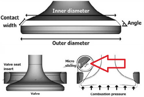
Image source: https://www.diva-portal.org/smash/get/diva2:1184646/FULLTEXT01.pdf
The top and left-hand bottom images are largely self-explanatory, but the image in the right bottom corner needs some explanation. Here is what it shows, but note that the details are greatly exaggerated for clarity-
You will notice that the valve head is shown to be concave, which (in large diesel engines that have large diameter valves) happens as a result of both the force acting on the valve when it closes and the effect of extremely high combustion pressures that literally “bend” the valve head.
Note the small red circle that indicates a relative sliding motion between the valve head and the valve seat as a result of the deformation of the valve head. In this particular example, the valve has an outer diameter of 40mm, an inner diameter of 37mm, and a 45-degree sealing surface. These dimensions yield a contact width of 2.1mm, a total contact/sealing area of 257 square millimetres, while the maximum allowed recession before the valve becomes inoperable, is 1.5 mm.
Now here is the interesting part; if we assume an operation life cycle of one billion operation cycles for this particular valve, the amount of valve recession caused by the relative sliding motion comes out at 0.015 Angstrom unit* per cycle.
* In scientific terms, an angstrom is aunit of length equal to one hundred-millionth of a centimetre (10?10 metre), and is used mainly to express wavelengths [of light] and inter-atomic distances.
As a practical matter, this translates into the combined removal of a layer of material that is one molecule thick every 18 seconds when the engine is running at 1300 RPM. Therefore, if we take a maximum allowable recession of 1.5mm, the total amount of material removed from both the valve head and the valve seat comes out at a volume of 272 square millimetres. Even more interesting is that if one adds up the total length of all micro sliding events that caused this valve to wear to its maximum allowable limits, the valve will have "moved" by just more than 10km.
Also, consider this: typical combustion pressures in large diesel truck engines are about 160 bars, which in the case of our example valve, yields a contact pressure of 20.1 kN, which is equal to placing a contact pressure of 2000 kg on an area with the surface area of a small coin. Moreover, the valve must endure these conditions for up to one billion times while the temperatures of the contact areas hover at around the 600 degree Celsius mark while allowing only 1.5 mm of wear to occur before the valve fails to contain the combustion pressure, which brings us to-
While the loads on valves in petrol engines are vastly smaller than those in large diesel engines, micro sliding between valves and valve seats also occur, albeit for different reasons, which we will discuss in some detail in the following section. Moreover, as with large diesel engines, the valves in petrol engines also have maximum allowable wear limits, but unlike large diesel engines, the range of allowable valve recession in petrol engines are specific to each engine type and design.
Although the valves in petrol engines are not as heavily loaded as those in large diesel engines are, the contact areas between valve heads and valve seats in petrol engines are much smaller than in large diesel engines. While this translates into slightly higher rates of wear, and especially after lead was removed from petrol when wear rates increased by between 10 and 20 times, increasing the thickness of valve heads by about one millimetre proved effective in reducing valve wear rates to acceptable levels.
We need not delve into the mathematics of why this worked here, but suffice it to say that the valves in modern petrol engines typically perform to specifications for about 300 000km or so before failing as the result of excessive wear. Nonetheless, like the valves in large diesel engines, the valves in petrol engines have to live their lives without deliberate lubrication, so let us look at-
We mentioned elsewhere that micro sliding on valves in petrol engines valve occur for different reasons than it does on large diesel engines. While the causes on diesel engines involve enormous pressures, the primary causes of micro sliding on petrol engines involve the dynamic clearances between valve stems and valve guides that prevent full conformal contact between the valve head and valve seat during each operational valve cycle. Put differently, this means that in petrol engines, all valves close in slightly different positions relative to the valve seat’s sealing surface during most valve cycles.
Lack of space precludes even a cursory discussion on the decades-long history of research into valve wear issues and the often-failed attempts to mitigate valve wear, except to say that in 1967, one researcher, a certain E.F. Wilde, came to the conclusion that-
“One of the most perplexing wear problems in internal combustion engines concerns valves. A study of the literature will reveal that practically every engine builder or user has had his share of valve wear problems. No hard and fast rules can be given to arrive at a satisfactory valve life. Each case must be painstakingly investigated, the cause or causes isolated and remedial action taken.” Source: https://www.diva-portal.org/smash/get/diva2:1184646/FULLTEXT01.pdf
This statement begs the following questions-
Answering each of these questions could fill several volumes, but fortunately, we don’t have to do that because Robin Elo, a researcher from the University of Uppsala in Sweden wrote a doctoral thesis about this very issue in 2018.
Much of this thesis describes highly technical issues, but limited space precludes a discussion of most of these topics, such as the construction and calibration of the test equipment. Therefore, we can only focus on the primary research that solved the problem of valve wear, or the lack of valve wear, in both diesel and petrol internal combustion engines, so let us look at-
In scientific terms, tribology is the study of friction, wear, lubrication, and the design of bearings, as well as the science of interacting surfaces in relative motion. Somewhat surprisingly, it turns out that one of the effects of tribology on valves and valve seats is that a thin protective film forms on valve heads’ sealing surfaces during the normal operation of an engine.
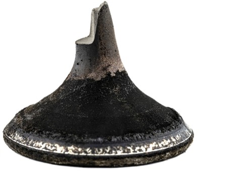
Known as “tribofilms” (short for “tribologically derived deposits”), these extremely hard and durable deposits on the sealing surfaces of valves typically build up to thicknesses of a few microns. An example of such a tribofilm is shown below-

Image source: https://www.diva-portal.org/smash/get/diva2:1184646/FULLTEXT01.pdf
In this example, the horizontal lines in the light-coloured patch are tool marks left behind during the valve’s manufacturing process. The dark-coloured material that overlays the valve surface is largely made up of carbon that is mixed with a variety of oil additives. In this case, the film is largely a mixture of carbon, boron, and several forms of zinc, which act as friction modifiers in engine oil.
While the thickness and composition of tribofilms are largely dependent on the engine type and fuel used, it turns out that the quality of the engine oil in an engine determines both the rate of formation and the rate of decay of tribofilms on valves and valve seats in all engines. Here is how this works-
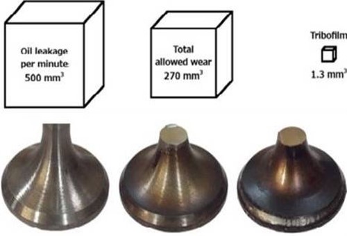
Image source: https://www.diva-portal.org/smash/get/diva2:1184646/FULLTEXT01.pdf
This image shows the progression of the formation of a tribofilm. The box in the top left-hand corner represents the volume of oil that leaks through the valve guides, as well as uncombusted oil that remains on the cylinder walls of a large diesel engine during one billion valve cycles. Note the dark appearance of the sealing surface of the valve in the middle- this is not evidence of valve burning: this is a tribofilm that had built up on the valve during the time it took for the valve to reach its maximum allowed wear limit. The small box on the top right-hand corner represents the total volume of the tribofilm relative to the surface area of the conformal contact area between the valve head and the valve seat insert.
We mentioned oil additives elsewhere, and it is, in fact, some of the additives in engine oil that eventually form protective films over the sealing areas of valves and valve seat inserts. While the actual mechanisms that transform additives like boron, zinc, various esters, and even silicon into protective films is still a little unclear, the research shows that the sulphur content of engine oil determines how fast tribofilms on valves form and wear away. Consider the panel of images below-
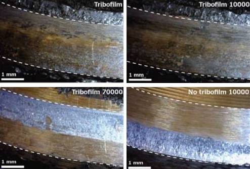
Image source: https://www.diva-portal.org/smash/get/diva2:1184646/FULLTEXT01.pdf
The image at the top left shows detail of a fully formed and established tribofilm on a valve. The image at the top right shows the same valve, but in this case, the tribofilm had been deprived of oil additives for 10 000 valve cycles. As shown here, the tribofilm is extremely durable, since it is still largely intact after 10 000 valve cycles.
The image at the bottom left shows the degradation of the same tribofilm after being deprived of oil additives for 70 000 cycles, which has caused the tribofilm to wear away to the point where the underlying metal of the valve head becomes visible. The image at the bottom right shows the extent to which the metal of the valve head had worn away only 10 000 cycles after the metal of the valve head had become exposed.
We can illustrate these processes with another example, so consider the panel of images below-
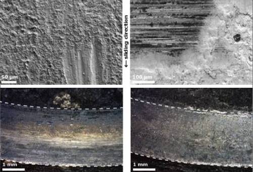
Image source: https://www.diva-portal.org/smash/get/diva2:1184646/FULLTEXT01.pdf
The three deep vertical scratches in the image at the top left corner are greatly enlarged details of the bottom right image in the previous panel. In this case, the scratches were caused by repeated micro sliding events between the valve and the valve seat insert. The image at the top right shows details of the underlying surface of the valve, as well as a grain of carbon (the black dot) that had become embedded in the tribofilm, which incidentally, had begun to flake off. In this example, the tribofilm is rendered in white to highlight the presence of the black carbon grain.
Nonetheless, the two images at the bottom are particularly interesting. In this example, the tribofilm on the left is well established, but it was formed by an oil formulation with a relatively low sulphur content to satisfy Euro 6 emission regulations. In contrast, the image at the bottom right shows a tribofilm that is considerably thicker and denser than the one on the left. In this case, the tribofilm was formed by additives in oil that had almost three times the sulphur content of the oil that conformed to Euro 6 standards.
These and other results were compared with valves removed from real engines, and in all cases, the test results correlated almost exactly with test results obtained from real engines that were operated under the same conditions as the test equipment.
Moreover, chemical testing of tribofilms and advanced analytical methods showed that the additives in the minute quantities of oil that seep down through valve guides to lubricate the valve stems are the principal "building blocks" of tribofilms on valves in all engine types and designs. In addition, several chemical analyses also showed that while different additive packages in different engine oil formulations affected the chemical composition of tribofilms somewhat, the rates of deposition and decay, as well as the durability of tribofilms on valves are directly proportional to the sulphur content of any given oil formulation.
So what does this mean in practice? It simply means this- unless metallurgists and engineers develop metals from which to fabricate affordable valves that do not need tribofilms to survive the harsh operating conditions that valves endure, the only way to prevent valves from burning away is to supply them with a constant stream of polluting oil additives through the valve guides, which leaves us with this-
So, there we have it; the solution to the question of why engine valves don’t melt or burn away in the absence of deliberate lubrication of their contact surfaces with valve seats.
However, it is important to remember that tribofilms on valves do not represent a form of lubrication. The only thing that tribofilms do is to prevent direct metal-to-metal contact between two contact surfaces to prevent boundary lubrication conditions from occurring between the valve head and the valve seat insert.
Of course, engine valves sometimes do burn and leak, but this is almost always caused by gross deficiencies in one or more parts of the valve train, as opposed to a complete lack of lubrication between valve heads and valve seats. And, of course, our sometimes-misguided efforts to remove the dark deposits on valve and valve seat sealing surfaces that we often see as evidence that valves are “not sealing properly” when we assemble cylinder heads.