Although ADAS (Advanced Driver Assistance Systems) are appearing in an ever-increasing number of new vehicles each year, these systems are arguably among the least understood automotive systems we as mechanics and technicians have to deal with. There are various reasons for this, not least of which is the fact that a modern high-end vehicle can contain more than a dozen of these systems, most of which go by different names on different applications.
Nonetheless, while there is a plethora of proprietary names for systems like Traction Control, Lane Departure Warning, Autonomous Braking/Steering, Blind Spot Monitoring, Accident Mitigation and many others, all ADAS systems largely use the same technologies based on the largely the same types of sensing devices.
More to the point though, all ADAS systems depend on very precise calibrations of various aspects of each system to function at all, and while we have all calibrated steering angle sensors, calibrating radar and other signal generating devices is an entirely different matter. Thus, in this article, we will take a closer look at some aspects of how ADAS systems work, and whether we, as independent workshops can, or should get involved in ADAS system calibration procedures, starting with this question-
In short, since limited space precludes a more complete treatment of the topic, ADAS systems can be described as a class of systems that is designed to either relieve a driver of some of the more tedious aspects of driving, such as keeping a sharp lookout for pedestrians and other obstacles, or to intervene in the driving process by assuming partial or full control of the brakes, steering and other control functions in emergency situations.
However, since not all possible ADAS systems are available on all vehicles, the SAE (Society of Automotive Engineers) has devised a classification scheme that describes the levels of automation on different vehicle classes. It is perhaps interesting to note that especially in the North American market this classification scheme has become a major, if not the ultimate deciding factor that determines consumer behaviour in terms of car purchases. Nevertheless, ADAS systems are classified as follows-
Vehicles that fall into categories 2 - 5 do not only need sophisticated software; these vehicles also require hardware that include video and infrared cameras, ultrasonic sensors, radar signal generators and antennas, and in some cases, LIDAR* (Light Detection and Ranging) generators and antennas.
* LIDAR systems use pulsed laser beams to measure distances to objects in the same way that RADAR uses pulsed radio waves to measure distances.
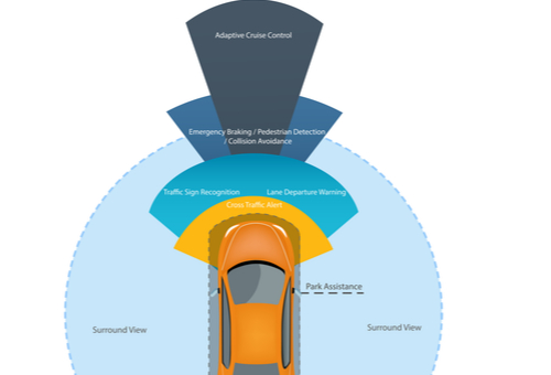
It should be noted though that in order to generate a 360-degree “view” of the area surrounding an ADAS-equipped vehicle, the data output of most, or all of the above mentioned sensors and signal generators are combined to create a multi-dimensional electronic map of the road ahead, as well as to facilitate real-time detection of different classes of obstacles that may be alongside or behind the vehicle. In the latter case, it should be noted that modern ADAS-based detection systems can differentiate between pedestrians, bicycles, road markings, and stationary traffic signs, as well as between various classes of vehicles such as trucks, motor cycles, cars, and buses, but particularly between normal vehicles and emergency vehicles, which begs this question-
Since limited space preludes a comprehensive discussion of all types or classes of ADAS detection technologies, this article will focus on radar signal generators, since these are used in several types of ADAS systems, including Autonomous Braking, Collision Mitigation, Lane Departure Warning, and Adaptive Cruise Control systems, among others.
In practice, radar signal generators and detectors are divided into two main types, these being Short Range Radar (SSR), and Long Range Radar (LRR) that are combined to provide a more complete picture of what is happening both in front and behind a vehicle, so let us first look at-
Short Range Radar Sensors
Short range radar sensors on automotive applications are typically of the ultra-wide band variety, due both to their higher resolution over short distances, and their relatively low cost. As a general rule, this type of radar sensor operates at frequencies below 77 GHz, and are typically used in systems such as-
Note that short range radar can monitor a distance of about 30 metres in front (and sometimes behind) of a vehicle in a cone-shaped pattern that subtends an angle of up to 80 degrees.
Long Range Radar
Long range radar typically operates at 77 GHz, and usually extends out to a distance of 150 metres in front of a vehicle, at which point the radar signal will cover three traffic lanes. On most automotive applications, long range radar systems use multi-beam antennas to measure the angle, range, and relative (radial) velocities of all moving obstacles in front of the vehicle to create an electronic map of the traffic flow. In most applications, a long-range radar signal can detect a smaller vehicle in front of larger one either by passing underneath the larger vehicle, or through the larger vehicle’s windows.
Long range radar typically forms the foundation of Adaptive Cruise Control systems, and particularly of Adaptive Cruise Control systems with active brake assist functionality. While “normal” adaptive cruise control systems generally operate the brakes in a smooth and predictable fashion, the various forms of active brake assist systems, including full autonomous braking and electronic brake distribution systems, can all apply much higher braking forces than any human driver can, and they can do so much more quickly than a human driver can, too.
In fact, some forms of active brake assist systems can utilise the vehicle’s full braking capacity to bring a vehicle to a full stop while maintaining the vehicles’ stability by assuming full control over the ABS, steering, throttle, and the automatic transmission, if fitted. Nonetheless, in terms of specifics, automotive ADAS radar systems are further divided into two categories, these categories being-
Continuous-wave radar
Essentially, continuous wave radar transmits and receives returned signals concurrently. In practice, the system generates a sinusoidal oscillating wave that is transmitted by an antenna, with the same antenna receiving the reflected signal. The range (distance) to the target is calculated by measuring the Doppler shift between the transmitted and received signal. However, a more accurate result can be obtained by using frequency modulation, or a variation in the phasing of successive signals.
Since this method places a unique time stamp on each transmitted wave, the time interval between the transmission of a signal and receipt of the reflected wave can be measured and used as the basis for calculating the distance to a target. For the benefit of readers that are interested, the basic equation or formula for this calculation is given below-
R=cT2?ff2-f1, in which-
Pulse radar
Also known as Doppler radar, this system has the advantage that it is able to detect reflected signals that have very small amplitudes, which is useful in the detection of small objects amid the clutter of large objects or targets that return large-amplitude reflections. This type of system calculates distances to targets solely on the basis of the time delay between the transmission and receipt of reflected signals. For those with a mathematical bent, the basic equation used in this calculation is given below-
R=c?T2, in which-
Relative velocity of the target is based on the target’s Doppler shift, and is calculated using the equation below-
v=fd?o2, in which-
In terms of operating principles Doppler radars are semi-duplex, in the sense that they either transmit or receive a signal at any given moment. This results in a high degree of isolation between the transmitter and the receiver, which greatly increases the effective dynamic ranges of both the transmitter and the receiver, because the outgoing signals and incoming reflections do not interfere with each other. However, this type of radar system has the major disadvantage that it creates a “blind spot” around itself, the extent of which can calculated by the formula given below-
Rb=c(?p + ts)2, in which-
While the above is necessarily a somewhat over simplification of an exceedingly complex system, it should be obvious that by combining pulse Doppler radar and frequency-modulated continuous wave radar, it is possible not only to detect a wide range of both moving and stationary targets, but also to distinguish between large and small objects, which brings us to-
While there is no doubt that ADAS systems have prevented hundreds of thousands of traffic accidents and saved a great many lives over the past decade or so, ADAS systems also have severe drawbacks for both consumers and mechanics.
From the perspective of the average car owner, the maintenance costs that come with ADAS systems far outweigh the initial cost of the various systems that are fitted to an ADAS-equipped vehicle. Moreover, to ensure proper operation of all ADAS systems on a vehicle, it is crucially important that all signal generating devices and their associated antennas, as well as all types of cameras and ultrasonic sensors are calibrated precisely. In fact, proper calibration is the cornerstone of ADAS system operation, and even one sensor whose calibration is out-of-spec can cause the automatic deactivation of several ADAS systems.
Two examples of this will suffice: if for instance a minor fender bender moves a grille-mounted radar signal generator out of position by as little as a few millimetres, several ADAS systems, including the ones listed below, could be either deactivated, or disabled automatically-
and several others, simply because the various control modules that control these systems are deprived of accurate input data. More to the point though, several ADAS systems depend on the ABS system to work, meaning that not only is a driver deprived of the benefits of several ADAS systems, that driver only has normal braking at his disposal.
One other example involves cameras and other detection devices that “look” though the windscreen. If windscreens were flat, it would not matter if a replacement windscreen were not mounted in exactly the same position as the old one. The fact is though that the overall curvature of a windscreen is achieved by combining several inconstant radii in two dimensions, which has a direct bearing on how light passes through different parts of a windscreen.
In practice, cameras and other sensing devices that depend on light are incorporated either into the windscreen itself, or into pillars and/or rear-view mirror assemblies in such a way that the light that falls on them passes through the windscreen in as straight a line as possible. Where this is not possible, correction factors are programmed into the devices’ software during recalibration to compensate for aberrations in the way an out-of-position windscreen refracts light, in a way that is roughly analogous to how spectacles correct defects in our eyes in order to improve poor vision.
You may have heard the term “windscreen calibration” being bandied about, but note that the term is not technically correct, since a replacement windscreen is not actually calibrated. As a practical matter, the term refers to the fact that sensors that “look” through the windscreen need to be recalibrated because it is impossible to mount a replacement windscreen in exactly the same position as the original. Thus, if the recalibration procedure of implicated or affected sensors is not performed after a windscreen replacement several ADAS systems, including-
and several others may be deactivated or disabled automatically, also because their control modules are deprived of accurate input data. Note also that even routine maintenance procedures such as wheel alignments, and brake, steering, and suspension repairs can disturb the calibration of ADAS sensors and devices. In fact, merely jacking up a vehicle wrong can disturb the calibration and positioning of ultrasonic sensors mounted in bumpers and/or fenders, which could potentially cause the deactivation of ADAS systems like-
and others, again because various control modules are deprived of accurate input data. There are many other examples of situations and/or circumstances that could affect the calibration of ADAS sensors and devices, but listing these could fill several large volumes. Therefore, suffice it to say that all ADAS related sensors, cameras, microphones, and antennas on a vehicle need to be calibrated and positioned precisely for all ADAS systems to work as designed, which begs this question-

In theory, the calibration process is a relatively simple affair that involves placing the vehicle in a suitable environment before placing a variety of radar and optical targets in front of the vehicle, and then allowing a factory scan tool to perform the actual recalibration process.
However, as a practical matter, the recalibration process depends on both a suitable environment and the required targets being available, not to mention the fact that extensive dealer service information must be obtained even before the process starts, and herein lays perhaps the biggest issue that independent workshops have to overcome.
There is no doubt that in theory, the rapid proliferation of ADAS systems can be leveraged to create huge amounts of additional business, but from the perspective of most independent operators the reality is somewhat different, primarily because of the (sometimes) prohibitive costs associated with setting up and equipping a workshop to perform ADAS calibration procedures.
Note that while it is not the intention of this article to discourage independent operators from entering the ADAS system recalibration market, independent operators should take careful note of what follows before deciding whether or not to enter this potentially very lucrative area of car repair-
You need space, and lots of it
Exactly how much space you need to create a suitable calibration environment depends on the vehicle brands you plan to work on, since all manufacturers prescribe minimum clearances on all sides of the vehicle, and in some cases, above the vehicle as well. Here are two examples of such requirements-
Honda specifies that a large, level, and paved indoor area must be available and that this area is fitted with non-glare lighting. Moreover, this area must be free of any clutter to prevent interference with optical cameras, and free of metallic objects to prevent interference with radar signals. Additionally, this area must be exactly 3.9 metres wide, 1.5 metres high above the vehicle, and extend to a distance of 7.01 metres in front of the vehicle.
Lexus, on the other hand, prescribes a level surface that extends to a distance of at least 9.7 metres in front of the vehicle, but note that this area must also be at least 13.7 metres wide. This area must also be free of clutter and metallic objects that can interfere with optical and radar signals.
Other manufacturers have other requirements, but the point is that unless the minimum requirements in terms of space can be met, it is simply not possible to perform ADAS recalibration procedures.
You need extensive and expensive tooling
Limited space precludes a full description of all tooling required for all applications, but the list starts with a wheel alignment rack that is suitable for 4-wheel alignments, since on some applications, a 4-wheel alignment is a required procedure. In these cases, all ADAS sensors are calibrated with reference to the vehicles’ thrust line, meaning that unless the alignment procedure is performed, the recalibration procedure cannot be initiated.
Note that while wheel alignment equipment with built-in ADAS recalibration capabilities are now becoming available, there is as yet no wheel alignment equipment available that can replace all static and dynamic calibration procedures on all applications. Note also that in many cases, the static calibration process has to be followed by a dynamic process, in which a vehicle is driven under various operating conditions and traffic densities for a fixed amount of time or distance to complete or verify the calibration process.
In addition to an alignment rack, you also need all the optical and radar targets that are relevant to a specific vehicle. These targets include uniquely patterned surfaces and variously shaped metal targets- all of which are designed to be used on specific models, although in some cases, the same targets can be used for several models within a given model range.
While there are some companies in Australia that can supply modular (and largely generic target-mounting systems), the fact is that the actual targets can for the most part only be obtained from the vehicle manufacturer. Note that while some optical targets are available from a variety of internet resources, downloaded targets have to be scaled up to match OEM targets exactly in terms of their patterns and overall dimensions; note that if you get the scaling process wrong, the calibration process simply will not initiate because one or more systems will not recognise the target.
In addition to the correct targets, you also need vehicle-specific levelling equipment to ensure that especially radar signals are aimed so that they strike their targets at specified angles. Again, if a radar signal’s aim is off by a faction of a degree, the calibration process will either not initiate, or it will be interrupted until the affected signal’s aim is corrected.
You need access to OEM service information
In the case of ADAS calibration procedures, OEM service information typically includes ADAS related trouble code definitions, recommended diagnostic and repair information, as well as details on the placement of targets, in addition to details on how to prepare a vehicle for calibration, but there is good and bad news.
The good news is that there are several internet resources (even ones that Australian IP addresses can access) that specialise in this type of information and that supply this information independently of vehicle manufacturers. However, the bad news is that in order to access this information, you would need a rather expensive subscription and in some cases, to pay an additional fee for each query.
Be aware also that even if you are prepared to pay for relevant service information, you also need to invest in scan tools that are able to access, and actually recalibrate ADAS systems, which is something very few, if any generic scan tools can do to OEM specifications, no matter how sophisticated they are. Therefore, and since there is simply no way to perform a calibration procedure without OEM service information, suitable diagnostic equipment, and a large variety of vehicle specific tooling and targets, we have to ask ourselves this all-important question-
There is no simple answer to this question, but much depends on your core business. For instance, there are currently many windscreen replacement establishments in Australia that perform relevant calibration procedures, mostly because insurers often insist that certain systems be recalibrated after a windscreen replacement both to reduce their (the insurers’) liability, and to ensure that all ADAS systems in the vehicle work as intended.
Accident repairers are also often compelled by both insurers and vehicle manufacturers to perform after-repair scans and ADAS recalibrations to verify accident repairs, and in these cases, workshop owners were forced to assume great financial burdens in order to be able to comply with these requirements.
However, for independent shops that perform mainly mechanical repairs, it might not always be possible to assume financial burdens of this magnitude. In many cases, the costs of either renting a second premises or sacrificing a large percentage of their existing floor space will simply be prohibitive, especially given the fact that it is debatable whether or not vehicles with advanced ADAS systems currently form a large enough percentage of the national fleet to warrant the huge capital outlay required to set up a workshop with ADAS recalibration facilities.
What is certain however is that the number of ADAS-equipped vehicles on Australia’s roads will increase every year, and that soon, all mechanical repairs to steering, brake, and suspension systems will have to be verified via an extensive recalibration of multiple sensors and systems. In fact, in some jurisdictions this is already the case, and if this practice were to be introduced into the Australian independent repair industry, the profitability of many workshops will come under immense pressure.
Despite the challenges that ADAS systems bring, there is no doubt that ADAS systems and their maintenance requirements represent excellent opportunities to generate significant amounts of additional business for all types of independent workshops, but the practical reality is that not all workshops will be able to leverage this fact due to the very high set-up costs involved.
Nonetheless, for workshops that can afford the capital outlay it might just be worth the expense to investigate the possibilities now, before ADAS systems get so complicated that only vehicle manufacturers and their dealers will be able to diagnose, repair, and calibrate these systems.
