Even the most advanced hydraulic brake systems can be seen as “stand-alone” systems, despite their high levels of integration with engine and transmission control systems. Brake-by-wire systems on EV/HEV vehicles, on the other hand, are a very different beast altogether, since much of the braking forces on these vehicles are generated in their propulsion systems.
As a practical matter, brake-by-wire systems are so highly integrated into the propulsion systems of EV/HEV vehicles that it is sometimes difficult to tell where propulsion ends and braking begins during normal vehicle operation. Thus, in this article, which is the first in a two-part series, we discuss brake-by-wire systems in general terms to provide a background for a more technical discussion of these systems in Part 2 of this series. Let us start with this question-

Image source: https://www.searchautoparts.com/sites/www.searchautoparts.com/files/images/MA0116-UC3-Toyota-Regen-Braking-Chart.gif
Contrary to popular belief, brake-by-wire systems are not new; the technology was in widespread use in tramcars and electric trucks as long ago as the 1920s. What is new, however, are the complex control mechanisms that now regulate the operation of these systems in modern applications.
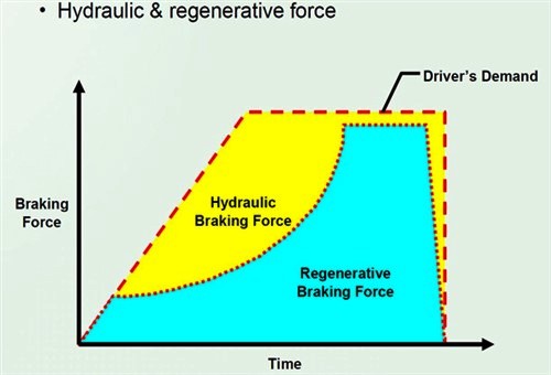
Consider the image above that shows the relationship between the amounts of brake force that is generated through regenerative braking (brake-by-wire) forces, as compared to the braking forces that are generated by the hydraulic brake system on a Gen III Toyota Prius. This example represents a single braking event, but note that while both hydraulic and regenerative braking forces are present in this example, the dotted line between the two forces represents a dividing line between the two forces. So what does this mean?
It simply means that depending on parameters such as road speed and the input force on the brake pedal, regenerative braking can sometimes exert a braking force on the vehicle that approaches that of the hydraulic brake system. In practice though, most drivers cannot distinguish between the contributions each system makes to slow down the vehicle; the only thing the driver is aware of is that the vehicle slows down when he presses down on the brake pedal.
Nonetheless, this does not answer the question of why brake-by-wire systems are needed on EV/HEV vehicles, so let us attempt a short explanation since a limited space precludes a comprehensive answer-
Electric vehicles have their own, specific rationale for existing, so in this discussion, we will focus on hybrid vehicles, which were primarily developed to reduce the overall amount of fossil fuels being burned in conventional vehicles as a means to reduce the environmental damage caused by exhaust emissions. Having said that, it must also be stated that hybrid technology does not increase the thermal efficiency of internal combustion engines; hybrid technology only makes internal combustion engines somewhat less inefficient in the larger scheme of propelling a hybrid vehicle, since some of the load on the internal combustion engine is relieved by one or more electric motors.
It would be fair to say that most of us understand the basic operation of hybrid vehicles, and we need not delve into the complexities of the various systems, components, and control mechanisms that make the technology work, here. Nonetheless, what is not well understood by many technicians is that the electric motors that supply much, if not all of a hybrid vehicles' motive power can also function as generators, simply by diverting battery current from the rotating part of the motor to the motor’s field coils.*
* Note that some online resources claim that regenerative braking on EV/HEV vehicles is based on the motor/generators on these vehicles “running in reverse” during regenerative braking. This is not true.
Switching or diverting battery current to the field coils has the effect of creating powerful magnetic fields in the motor, which have a powerful braking effect on the motors’ rotating part(s), which is what a driver experiences as a braking force on the vehicle. This force is what is represented in the blue part of the diagram at the start of this section.
The magnetic braking force is what is known as "regenerative braking", as the result of one form of energy, which is the vehicles’ kinetic energy in this case, being converted into electrical energy by the vehicle’s electric traction motor that is now working as a generator. Put in another way, regenerative braking is the process of “harvesting” kinetic energy that would otherwise have been lost to the atmosphere as heat created by the hydraulic brakes. The harvested energy is then stored in the battery pack for use later on to reduce the amount fuel the internal combustion engine would have needed to accelerate the vehicle again after the braking event.
So to answer the question of why brake-by-wire systems are needed; brake-by-wire systems greatly reduce fuel consumption of internal combustion engines, which is the primary driver behind the development of hybrid vehicle propulsion technologies in the first place, which begs this question-
To answer this question, we need to understand that the phrase “efficiency of [a] brake-by-wire” system means different things to different people. For instance, to marketers, the word “efficiency” typically refers to how much regenerative braking can extend the range of an EV, or improve the fuel economy of an HEV, which is a reasonable interpretation because these systems do extend ranges and improve fuel economy somewhat.
However, to technicians who have to diagnose and fix problems with brake-by-wire systems, such as, for instance, greatly increased stopping distances and overheated hydraulic brake components, “efficiency” means something else entirely. In this context, “efficiency” has to be judged against “effectiveness”, and while the two concepts may sound similar, they refer to two different aspects of a typical brake-by-wire systems’ overall ability to function as a means of slowing a vehicle down safely and effectively. Before we get to some specifics, let us consider the image below-

Image source: https://www.searchautoparts.com/sites/www.searchautoparts.com/files/images/MA0116-UC2-GEN-IIII-Pruis-Battery-SOC-Chart.gif
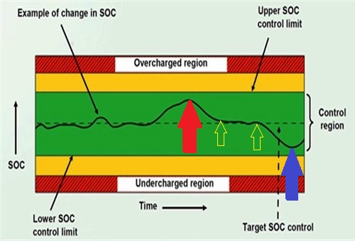
This image is a generic representation of what is known as a Battery State of Charge chart, and this example applies to a Gen III Toyota Prius. You may or may not know this, but the ideal state of charge of a typical hybrid battery pack is not 100%: in most cases, these batteries perform best and last longest when their state of charge falls in a range between about 60% and about 80%. In this example, this ideal SOC is represented by the wide green band.
The black dashed line running along the middle of the green band represents the ideal or desired charging rate and current, as opposed to the actual charging rate and current, which is represented by the wavy solid black line that follows the dashed line. Note though that this example is a representation of an actual braking event that is followed by a gentle acceleration event with some assistance from the internal combustion engine. Note also that in this example, the distance between the two small yellow arrows represents a period during the braking event in which the hydraulic and regenerative braking forces were roughly equal.
With that out of the way, we can focus more on “efficiency” vs. “effectiveness”, starting with-
Note the difference between the amplitudes of the spike that is indicated by the red arrow, and the dip that is indicated by the blue arrow- you will notice that the amplitude of the spike is noticeably smaller than that of the dip.
In practice, the spike and the dip, or least, the amplitudes of the two features are not related in meaningful ways. Nonetheless, the amplitude of the spike (red arrow) relates to the efficiency of the regenerative braking system in the sense that it reflects how much kinetic energy (generated by the moving vehicle) is harvested and converted into electrical energy, while the dip (indicated by the blue arrow), represents energy being withdrawn from the battery pack during the acceleration that followed the braking event.
It should be noted though that this example applies only to this particular vehicle and braking event, and is a reflection of the efficiency of the regenerative braking system under operating conditions that obtained at the exact moment that the readings were taken. These conditions include, among others, the following-
When taken together, the factors listed above typically account for conversion losses of somewhere between about 30% and 40% on most hybrid vehicles (and roughly equal losses on purely electric vehicles), which translates into efficiencies of about 60 to 70 per cent in terms of replacing lost battery capacity during a regeneration event, which brings us to-
The efficiency values stated above do not refer to the contribution a regenerative brake system makes to the overall stopping power of an EV or HEV vehicle; these values refer solely to how efficiently a particular regenerative braking system converts one form of energy into another. Therefore, the contribution that regenerative braking makes to a vehicle’s overall stopping power is purely a function of the relationship between electricity and magnetism, neither of which can exist without the other.
Nonetheless, although braking-by-wire is a function of a relationship between two physical forces, how effective it is as a braking mechanism is largely determined by the relationship between the level of sophistication of the control system, and the physical properties of the motor/generator.
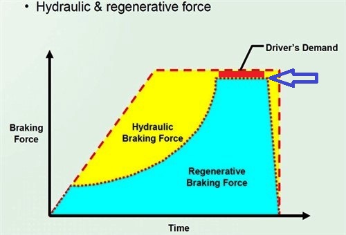
Thus, to understand “effectiveness” in this context, we need to consider this image again, but with one small modification, which is the small red rectangle that separates the yellow and blue portions of the graph-

Image source: https://www.searchautoparts.com/sites/www.searchautoparts.com/files/images/MA0116-UC2-GEN-IIII-Pruis-Battery-SOC-Chart.gif
This graph is closely related to the image of the battery SOC chart in the previous section and pertains to the same braking event. As stated elsewhere, the yellow part of the graph represents hydraulic braking forces, while the blue part represents regenerative forces, but what is noteworthy is the relationship between the two braking forces during a braking event. Here is how it works, but note that the hydraulic brake forces depicted here include the hydraulic braking forces delivered to the non-driving wheels, which forces are always proportional to the pressure being applied to the brake pedal by the driver-
We mentioned the small red rectangle earlier; in terms of the total braking forces acting upon the vehicle, this rectangle illustrates the small difference between the effect of the hydraulic brake system and the effect of the regenerative braking system in this particular braking event. While it is tempting to think that the regenerative braking system is usually almost as efficient as the hydraulic system, the truth is that it is the combination of the effects of the two systems that determines the overall stopping ability of the vehicle during a braking event under any given set of circumstances.
In practice, and depending on operating conditions when the braking event is initiated, the brake control module (aka brake controller) can and does vary the amount of regenerative braking relative to the force of the driver’s input on the brake pedal.
For instance, if the driver applies a low force to the pedal, the brake control module may not apply any hydraulic braking forces to any wheels and provided the controller calculates that the regenerative process will slow the vehicle down safely, only regenerative forces will brake the vehicle. Conversely, if the driver applies a force to the brake pedal that exceeds a pre-defined limit, the brake control module will apply the maximum available amount of regenerative braking to the driving wheels, while at the same time, applying a proportional amount of hydraulic braking force to both the driving and non-driving wheels.
Under these conditions, the brake control module will always maintain the regenerative braking forces at maximum allowable levels to recover as much kinetic energy as possible during that particular braking event, and in some cases, the regenerative braking force may approach the effectiveness of the hydraulic brakes. Nonetheless, as the vehicle slows down, kinetic energy decreases to the point where further recovery of energy is no longer viable or possible, which point is indicated by the blue arrow in the above diagram.
As can be seen, the effect of regenerative braking drops off very sharply after this point, which typically occurs when the vehicle slows down to a road speed of about 10 km/h. After this point, only the hydraulic brake system will be in operation either until the vehicle comes to a full stop or until the driver removes all pressure from the brake pedal, which brings us to the-
In Part 2, we will take a closer look at some design specifics of the regenerative braking systems on some EV/HEV vehicles in terms of componentry, and how various components interact with each other. We will also look at some basic diagnostics on regenerative braking systems in general, and at what to look out for when you are diagnosing or working on these systems, in particular.