Most of us who are not expert auto-electricians would like to think of ourselves as reasonably competent when it comes to diagnosing simple electrical issues such as resistance and continuity problems that do not involve control modules. However, if we were honest with ourselves, we must admit that most of us shy away from complex diagnostics that involve CAN bus serial communications systems, and with good reason. These systems can be extremely complex, intricate, and convoluted, which leaves plenty of room for mistakes, misdiagnoses, and expensive comebacks.
Having said that, CAN serial communications systems are not so complex, intricate, and convoluted that we can't learn at least the basics of what these systems do, how they work, and how they are set up to control the dozens of control modules in modern vehicles. More to the point though, knowing the basics of CAN serial communications networks allows us to not only recognise basic malfunctions and how to diagnose them, but also when to know when we are in way over our heads and need to call in an expert auto-electrician. In this article, then, we will discuss the general operating principles of CAN bus systems in easy-to-understand language, starting with explaining-
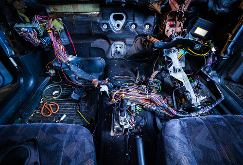
The oldest among us will remember a time when few cars had more than about eight (or fewer) fuses, and wiring harnesses were about as thick as the average human thumb. Each of the few electrical consumers in the cars of the time had its own dedicated circuit, and electrical diagnostics was easy because all you needed was a multimeter and 12V test light to diagnose almost any fault in seconds. These times could loosely be called 'the good old days".
Sadly, though, the good old days only lasted until the start of the 1970s, when consumer demand for all manner of gadgets, bells and whistles, and other creature comforts in cars, many of which consumed electricity, started to grow. These included power windows, power seats, sunroofs, clocks, and other instrumentation in dashboards, central locking, and others. This was also the time when talking about exhaust emission control became serious, and manufacturers started looking into the development of catalytic converters.
When ABS systems arrived in the mid-1980s, and fuel injection was widely adopted soon after, automotive electrical systems had become too complicated for each consumer to have its own dedicated circuit. Therefore, car manufacturers began to develop ways to integrate several circuits into one "mainline" circuit both to reduce the overall complexity of the electrical systems of the time and to reduce manufacturing costs. These integrations became known as "multiplex" systems, and while these systems were exceeding primitive by today's standards, multiplexing became the foundation on which the first true serial communications systems were built when OBD 1 diagnostic systems were introduced in 1991.
We need not delve into the details of the transition to OBD II here, beyond saying that when OBD II became mandatory in 1996, serial communications technology had reached the point where it could support complex engine and fuel management systems, in addition to the first iterations of ABS, cruise control, climate control, exhaust emission control, and complex instrumentation.
By the early to mid-2000s, however, the proliferation of new driver assists systems, as well as the demands of improved emission control systems (many of which were controlled by dedicated control modules) were beginning to overwhelm the capabilities of CAN (Controller Area Network) serial communications systems to manage communications between various systems and control modules. As a result, car manufacturers began to separate communications between systems and control modules into high priority, medium priority, and low priority categories to improve communications throughout the overall CAN bus system, and it is here where things can become confusing if you are not an expert on serial communications systems, so let us explore some basic-
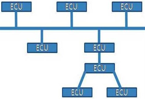
"Topology" refers to the architecture, or layout of a CAN bus system, with reference to how the control modules on a particular system are connected to each other. The most commonly used architectures are so-called "loops" in which the control modules are connected in a chain, and "stars", in which control modules are all connected to a common connection point, which is also known as a "shorting bar". The simplified schematic diagram shown above shows a hybrid system, with the control modules at the bottom right being connected in a star formation and those along the top of the diagram being connected in a chain formation.
From a diagnostic perspective, it is important to know how control modules are connected. For instance, disconnecting a control module in a chain formation might disable all the control modules on that chain, while disconnecting a module in a star formation will typically not affect the other modules in that formation. In practice, disconnecting modules in a star formation by turns is often the most effective way of isolating or identifying a defective control module.
In all CAN bus systems, each control module that is connected to a bus, or a branch of a bus, is typically referred to as a "node". Note, though, that when a scan tool is connected to the data link connector, the scan tool also becomes a node, because the act of connecting a scan tool to the system makes it an integral part of the CAN bus system. This is also true of the aftermarket telematics devices that some insurers use to measure/monitor driving behaviour, but the problem with these devices is that they are not always fully compatible with some communications protocols, which can sometimes result in unexpected, erratic, and unpredictable behaviour by some systems.
The technical differences between commonly used protocols such as UART, CAN, Flexray, and MOST are a highly technical subject, and limited space precludes a comprehensive discussion on the advantages and disadvantages of each. However, the easiest way to understand the differences is to think of protocols as different languages that can all be written with the Roman alphabet.
For instance, the same letters can be used to rewrite this article in French, German, Dutch, and many other languages, but each version of the rewritten article will differ from the original in ways that apply to each written language, although the overall message and content will be the same in all languages. For instance, the French version will have many diacritical marks and accents that do not apply to German or Dutch, while the German version will have letter substitutions that do not apply to either the Dutch or French versions.
In practice, while all communications protocols construct data messages that are transmitted over the CAN bus system by combining "1's" and "0's", no two protocols construct data messages in the same way, because some protocols are proprietary to some manufacturers. Overall, though, all data messages contain some basic information that is common to all protocols, even though the basic structure of the transmission may differ, in the same way, that translated documents contain the same information although they may appear to be different.
For instance, all data transmissions contain information that identifies both the transmitting module and all other control modules that should receive that transmission. This is followed by the actual data, such as information on the how fast the wheels are rotating, or the angle of the throttle plate. This part of the message is followed by a checksum, which is a tally of all the bits of information that comprises the entire transmission, including the information that identifies the transmitting and receiving modules.
All receiving modules check the transmission against this checksum value, and if this value deviates from what they had expected to receive, one or more receiving modules will set one or more "CHECKSUM ERROR" related trouble codes.
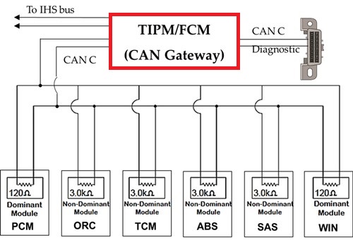
Image source:https://www.searchautoparts.com/sites/www.searchautoparts.com/files/images/ma0817-6e-copy.jpg
Gateway modules like the one outlined in red in this schematic are exactly what their name suggests- gateways between the CAN bus system and the data link connector. Note that while gateway modules are relatively rare on vehicles made before about 2004, the primary purpose of gateway modules on vehicles made after 2012/13 is to serve as a sort of translator that can translate any communications protocol to a common language to allow computer-based diagnostic software to communicate with all CAN bus systems via a J2534 pass-through device.
While it might appear that everything on a moving vehicle happens at the same time, there is a system in force on all CAN bus systems that strictly prioritises some data transmissions over others to prevent all the control modules in the system from "talking over" each other. Moreover, since each control module has a unique identifier, and all control modules are programmed only to respond to data transmissions that are intended for them, the arbitration scheme is greatly simplified.
Nonetheless, some types of transmissions are more critical to the safe and efficient operation of a vehicle than others are, so to separate high-priority messages from those that have a lower priority, most vehicles have several discrete communications systems. For instance, stability control systems and engine management functions have the highest priority, so these types of messages are sent over systems that can transmit as many as one million bytes per second.
Functions like infotainment and navigation are not critical to the vehicle's safe operation, so these transmissions are typically handled by medium speed systems, while exterior lighting will be controlled by a low-speed system. As a practical matter then, the control modules with the highest status will always be allowed to transmit their data first, before lower-ranking modules will be allowed to access the system to transmit their data.
While the above section might sound like a bit of useless information, the fact is that knowing the speed of a particular CAN system is sometimes critically important for diagnostic purposes. For instance, Mercedes and Chrysler are just two examples of OEM manufacturers that specify the speed of CAN systems in their service information as a diagnostic aid. Note though that CAN transmission speeds can be expressed in one of two ways, either as a baud rate* or as a kilobyte per second rate.
* The two expressions say the same thing: a baud rate is the maximum number of bytes that can be transmitted over a network in one second, while kilobyte per second is self-explanatory. For example, a baud rate of 8 100 is equal to 8 100 kilobytes per second. Below are some examples of CAN speeds in common use-
While the above sections do not pretend to be a master class in CAN bus systems and their operation, it should nevertheless give you a better understanding of how these systems are constructed and how they work. However, this article would not be complete without a short overview of what to look out for when you encounter communications trouble codes, so let us look at-

This image shows a twisted wire pair, which lies at the heart of why CAN bus systems work as well as they do. By twisting the wires around each other at a particular frequency, (typically one twist per 2.5 cm or so), referencing the wires to each other, and then inserting a resistor between the wires at their ends, it is possible to transmit large amounts of data with negligible amounts of electromagnetic interference. The two images below illustrate this point-
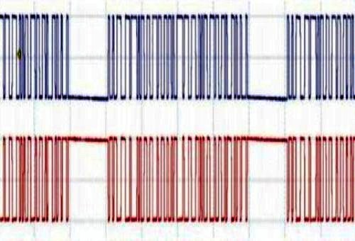
In this example of a scope trace of a CAN system at rest, the two lines of the CAN system are mirror images of each other. If the system is free of defects, whatever happens in one line will always be reflected in the other line. The image below shows what this looks like in a CAN system that is actively transmitting data-
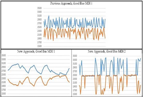
Image sources: https://www.searchautoparts.com/sites/www.searchautoparts.com/files/images/ma0817-14e-copy.jpg
Note that while the traces in the bottom right panel are not exact mirror images of each other, the slight differences are the result of small voltage spikes and other anomalies that are common in high-speed data transmissions, and therefore, these differences can be disregarded. What you are looking for are signal dropouts in one of the lines, or major deviations that occur in a fixed or recurring pattern, which could be the result of COP (Computer Operating Pulse) resets, which is common on Chrysler vehicles when the ASD (Auto Shut Down) relay fails or malfunctions.
However, these kinds of failures, defects, and malfunctions are relatively rare, and in many, if not most cases, CAN bus issues can be diagnosed and resolved relatively easily. Here is what to look out for-
Power and ground connections
Although the two CAN lines are not referenced to ground, the control modules they connect depend on sufficient current and a proper ground connection to work properly. Check ground and power circuits by performing voltage drop tests on suspect circuits, but be sure to load the circuits undergoing testing with a substitute load that equals the current draw of the affected control module.
Electromagnetic interference
Use an oscilloscope to check for excessive AC ripple current in affected circuits. Also, check for damage to high-speed wiring that could induce excessive electromagnetic interference, if such damage is found the recommended remedy is to replace the damaged sections of wiring with a new OEM harness because disturbing the twist on the lines could induce excessive electronic noise, even though the repair itself might be perfect.
Failed termination resistors
The function of termination resistors in the ends of CAN bus lines is to prevent signals from reflecting back and forth through the system. Failure of these resistors can cause a wide variety of CAN issues, so whenever you encounter multiple communications codes and erratic or intermittent symptoms, verify that the terminal resistance on high-speed lines is about 60 ohms when measured between pins 6 and 14 in the data link connector. Replace the resistors if measured values exceed specified values by about 10%.
Corrupted or outdated software
Corrupted software accounts for a significant percentage of CAN bus failures and/or malfunctions. In theory, these kinds of issues can often be resolved by reprogramming, but the problem is that in most cases, you need a factory scan tool to perform the reprogramming. Moreover, programming or software issues can often not be identified even with high-end generic scan tools, so if you suspect that you might be dealing with a programming or software issue, the best option might be to refer the vehicle to a specialist repairer if you do not have access to a factory scan tool, which leaves us with this-
While the complexity of current CAN bus systems should not be underestimated, they are not so complex that non-experts should always avoid working on them. With a working knowledge of their basic operating principles, a solid, well-though-out diagnostic strategy, and an accurate wiring diagram, it is possible to diagnose and resolve many CAN-related issues that would otherwise have been referred to dealerships and other specialist repairers. Are you ready to take up the challenge?
