While most aftermarket ignition coils resemble OEM coils in all respects, the fact is that many aftermarket coils just do not deliver the same performance that OEM or OEM-equivalent coils do. Thus, while all of us have encountered and resolved misfires that involved ignition coils, not all of us have learnt the lesson that ignition coils are not created equal.
This article will recount a case of new, but bad coils that caused intermittent misfires on a 2015 Toyota Corolla. This tale also involves one of the Three Young Mechanics, whom this writer has featured before. Long story short: one of the three young mechanics had found formal employment in another small workshop, and one of his first jobs at his new workplace involved diagnosing the Toyota Corolla that began to misfire randomly on all four cylinders as soon as the engine warmed up.
Based on the young mechanics’ recommendation, his new (recently-qualified-as-a-mechanic) employer invited this writer to consult on the issue. Here is what he found, but before we get to specifics, let us state-
At first glance, the Corolla was in excellent condition, and according to the young mechanic, the car had received all of its scheduled services at a dealership while it was under warranty. When it came out of warranty, the owner had kept up with regular servicing, and the service history was available for inspection.
The young mechanic also stated that according to the car’s owner, the misfire problem had gotten worse after another workshop had replaced all four coils when one of the original coils had failed. Also according to the owner, the set of coils in the vehicle was the second set after the original OEM coil had failed less than three months before. Despite this, the young mechanic held the opinion that replacing the coils yet again was the best option at this point, because as he put it, “...everything else seemed to be OK”.
As a further affront to common-sense ignition coil diagnostics, the young mechanic also boldly stated "...there was no point in scoping the coils because swapping them around several times did nothing because the OBD system kept on setting random misfire code P0300". Asked to clarify this statement, the young mechanic bravely stated that as far as he was concerned, the coils are fine, and therefore, there must be some kind of problem in the primary circuits.
In the interest of brevity, we can gloss over the details of the discussion that followed but it was blindingly obvious to this writer that despite the young mechanic’s training, he had no idea how to diagnose the problem. Therefore, to satisfy himself that there was indeed a problem with the Corolla, this writer took a closer look. Here is what he found-
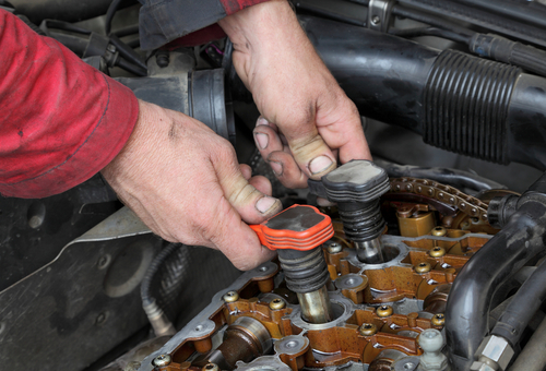
Upon closer inspection, all four coils were indeed new, so this writer inspected the electrical connectors. All seemed to be OK- there were no broken, bent, damaged or corroded pins or terminals, and all locked securely onto the coils, which largely ruled out bad connections.
Since the engine was cold, this writer fired it up and allowed it to run at idling speed for a few minutes to warm up. Sure enough, as soon as it warmed up, it began to misfire. However, contrary to what the young mechanic believed, it is exceedingly rare for the primary circuits of all four coils to fail at the same time. Therefore, the problem was more likely to involve substandard coils than anything to do with their primary circuits.
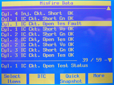
There was, however, no information available on how much the replacement coils cost, which would have been a reasonably good indicator of their quality. Thus, the quickest way to test the command pulse circuit was to connect a scan tool and to remove the chassis ground wire from the coil on cylinder #1 while the engine was running. Here is what the tool showed-
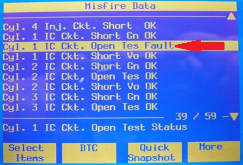
Image source: https://www.underhoodservice.com/wp-content/uploads/Articles/03_01_2009/89493Figure9jpg_00000044256.jpg
Since some Toyotas, including this particular Corolla, use a particular "flavour" of a four-wire coil, the result shown here was expected. Here is why-
Of the four wires on some Toyota coils, one supplies power at 5 volts, one is a ground to the chassis, and another delivers the command signal/pulse from the ECU. The fourth wire is known as the “IGF” (Ignition Feedback) circuit, and it connects all the coils in parallel. This circuit carries a 5-volt reference circuit.
Since each coil has its own dedicated diagnostics circuitry, the ECU uses the 5-volt circuit as a means to confirm the delivery of a command signal to each coil, all the coils being connected in parallel with this circuit. In practice though, when a coil generates an ignition spark, the diagnostic circuitry in the coil grounds the IGF circuit briefly as a way to confirm to the ECU that the coil had indeed generated a spark.
As a practical matter, removing a coils’ chassis ground wire will not affect the command pulse and diagnostic circuits, but the ECU will not receive a confirmation on whether (or not) the coil had indeed produced an ignition spark. In this case, it did not receive confirmation (of a spark) from cylinder #1, and it set a misfire code specific to cylinder #1- as expected.
The other information on the tool's display showing open and short circuits in the other coils confirmed this writer's suspicion that the coils had not failed at the same time. These coils were just bad from the start since removing the chassis ground wire from the other coils produced cylinder-specific misfire codes.
To reinforce his diagnosis of bad coils, this writer placed a KV probe on each coil, which clearly showed just how randomly each coil was misfiring, even though each coil’s command pulse and diagnostic circuits worked perfectly. However, this diagnosis met with some resistance from the young mechanic, who now inclined to the belief that the spark plugs may be causing the coils to misfire.
Although this is not altogether impossible, it was highly unlikely to be the case, and this writer said so rather forcefully. Thus, to resolve the issue, this writer offered to pay for a set of new sparkplugs that was duly installed but, which, as expected, did nothing to resolve the misfire problem. In the meantime though, the misfire problem had gotten progressively worse as the engine got progressively hotter.
After some more back and forth between this writer and the young mechanic’s employer about bad coils versus good coils, the employer agreed to replace the coils on the Corolla with OEM parts. As expected, this resolved the issue definitively: the random misfires disappeared and no new misfire (or other) codes had been set after an extensive test drive.
As diagnoses go, this one was quick and easy because when the problem was reduced to its simplest form, the solution became obvious- or it should have been obvious even to a relatively inexperienced mechanic. OEM coils or even high-quality OEM-equivalent aftermarket coils simply do not all fail at the same time. The only way this happens is when something else, such as the primary circuits of all the coils on the engine break down at the same time, which typically only happens when an engine management ECU or a crankshaft position sensor fails.
In both cases, there will be specific signs, symptoms, and trouble codes present, which settled the matter because none of the expected signs, symptoms, and trouble codes was present.
However, cheap, substandard COP ignition coils can, and sometimes, do fail all at the same time. More commonly though, they simply do not work as they should from the moment they are installed. So how do you always tell the difference between good and bad COP coils, especially when you did not install them, or know what they cost?
Telling the difference is admittedly not always easy when you compare coils visually. However, knowing how each type of coil works, and how to diagnose each type of coil is often the only way to tell the good from the bad and the ugly.
What follows may be considered preaching to the converted, as it were, but if you are still learning to find your way around ignition circuits, we hope that you find the following sections on COP ignition coil operation and diagnostics helpful and informative. However, the sections below assume that the primary circuit of each type of coil is working as designed and that you have verified this fact before proceeding. Let us start with-
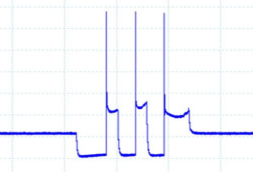
Image source: https://www.underhoodservice.com/wp-content/uploads/Articles/03_01_2009/89493Figure3jpg_00000044242.jpg
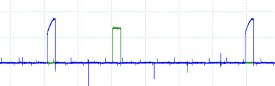
Two-wire COP coils are so-called because there are two terminals in their connectors, and the waveform example shown here shows a two-wire coil that is working as designed. Here is how two-wire coils work-
One of the terminals on the coil connects to a ground that is supplied by the ECU. When the ECU grounds this terminal, the coil is ”triggered” to begin accumulating a charge in the primary winding. However, although high-quality two-wire COP coils are considered Ohmic loads because they follow Ohms law exactly, the ultimate current (amperage) in the coils’ primary windings is not always constant in consecutive cycles.
This variation is normal, but the degree of variability is influenced by-
An example of this variability is shown in the waveform above. While the small variations between successive ramp-up/discharge cycles are not big enough to be of concern, both random and cyclical large deviations from a median value are usually indicative of a defect in the coil.
Note also that a), the ignition timing/ignition control electronics is always located in the ECU, and b), that the ECU is always the driver of ignition events. In practice, the ECU always provides the coil's ground, while the 12-volt current that powers the driver circuit in the ECU can derive from a dedicated ignition relay on older models, or an ASD (Automatic Shutdown) relay in newer models. Note that verifying the integrity of the driver circuits' power supply should always be the first step in diagnosing two-wire COP coil issues. Here is-
How to diagnose two-wire COP coils
Assuming that the primary circuit is working, proceed to test the resistance of the primary winding across the two terminals in the connector. A good value would be around 1 Ohm (or a bit less: readings of around 0.1 Ohm would indicate a short circuit in the primary winding, while an open circuit would yield no reading.
You can also test the resistance f the secondary winding between any of the terminals in the connector and the coil’s output to the spark plug. A good value would be a few thousand Ohms, while a reading of only a few Ohm is usually evidence of a short circuit, which typically produces a no-spark condition. However, open circuits may be caused by small breaks in the windings that could have two possible effects.
The first is a possible permanent no-spark condition, and the second may be intermittent misfires that occur only under specific operating conditions. For instance, since high currents can jump across small gaps, the coil might still work when it is cold, and stop working when high temperatures increase the gap in the winding. Note though that intermittent misfires caused by breaks in the secondary winding can be influenced by the engine speed/load, as well as by air/fuel ratios.
Many two-wire COP coils feature a diode between the two terminals. These diodes are intended to prevent inductive voltages from leaking back into the primary circuit, so be sure to check service information if such diodes are present n the affected model, and be sure to test the condition of this diode before condemning a COP coil out of hand when you find open circuits. Note though that these diodes cannot be replaced- you have to replace the coil if you encounter a blown diode, which brings us to-
How the ECU diagnoses two-wire COP coils
Apart from the monitoring misfires with the conventional misfire detection system via the crankshaft position sensor, an ECU also checks for misfires in two other ways.
The first is by monitoring the current draw for each coil, which typically falls into a very narrow range. Excessive current draws usually indicate short circuits, while insufficient, or no current draws indicate open circuits.
The second way is by confirming inductive voltages with the Zener diode placed between the terminals in the connector. While Zener diodes block reverse voltages just like any other diodes, Zener diodes are rated to block reverse currents only until a pre-defined voltage is reached. Thus, when the inductive voltage reaches this limit, the ECU detects the voltage and interprets it as confirmation that the coil had successfully produced an ignition spark. A lack f such confirmation is interpreted by the ECU as a coil failure.
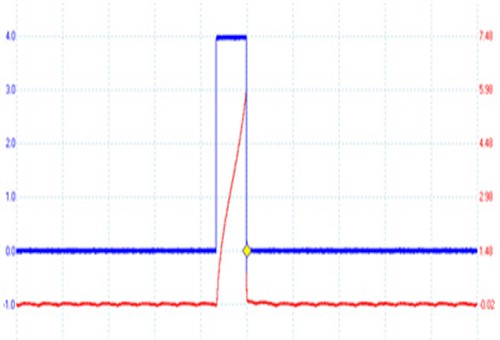
Image source: https://www.underhoodservice.com/coil-on-plug-ignition-the-wired-differences/
This waveform is representative of all three-wire COP coils, which have largely replaced all two-and four-wire COP coils on most new models of most car brands.
As a practical matter, three-wire coils have three terminals in their connectors. One carries 12-volt power, another is an input from the ignition control/ignition timing circuitry in the ECU, and the other is a ground. While most three-wire COP coils do not have a connection between their internal circuitry and the retaining bolt eyelet, the three-wire coils made by Delphi on some GM models require that a separate chassis ground be connected to the retaining bolt eyelet.
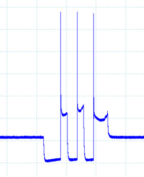
Note though that while three-wire COP coils are now the most common design across all applications, diagnosing these coils can be tricky because the shape of the only waveform you can obtain is more important than any other diagnostic criterion. Consider the waveform above-
Since one cannot scope the primary voltage, or test the resistance of the primary winding, one can only scope the primary circuit, such as the example above. In this example, the blue trace represents the dwell, or ramp up time, while the red trace represents the command signal.
Observant readers will notice that the command signal and the ramp-up times are equal in terms of duration. Thus, since switching the primary circuit "ON" to start the ramp-up, and "OFF" to discharge the coil is done by integrated circuitry in each coil, the ECU uses a numerical version of the waveform above to monitor the operation of each coil.
Note also that since the actual dwell time and command signal durations differ between makes and models, the only way to diagnose three-wire coils with an oscilloscope is to scope all the coils on the engine, and then to compare the waveforms from all the coils to identify the defective coil(s). Below is an example of a waveform showing a defective coil that is producing intermittent misfires, with the misfire event circled in red-
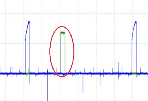
Image source: https://www.underhoodservice.com/wp-content/uploads/Articles/03_01_2009/89493Figure6jpg_00000044247.jpg
Although four-wire COP coils are now relatively rare, they are still common on some GM products. One wire carries a 12-volt current, one is a chassis ground, and one is known as the IC circuit that carries the command pulse/signal from the ECU. The fourth wire is known as the "low reference" circuit that emanates from the ECU and this is a "cleaner" ground than most other ground circuits.
In practice, the two ground circuits are separated from each other; the chassis ground circuit serves the primary ignition circuit, while the low reference circuit serves the coil’s internal circuitry. As a practical matter though, most GM four-wire coils incorporate a kind of fail-safe mode, in the sense that if one ground circuit fails, the remaining circuit can serve both the primary circuit and the coil’s internal circuitry. Note, also, that on some versions of GM four-wire coils, the retaining bolt eyelet functions as the chassis ground.
In terms of misfire detection, the ECU monitors the IC circuit for open circuits, as well as for short circuits to both ground and power. For instance, if the coil is disconnected to simulate an open circuit, the unloaded command pulse circuit will measure between 4.9 volts and 5 volts, but if the coil is reconnected, the voltage will drop to 4 volts, or sometimes, to a little under 4 volts. Thus, if the ECU detects that the voltage in the command pulse circuit had dropped to a minimum 4-volt threshold, it will interpret the voltage drop as a coil performance issue and set a misfire code for the affected coil/cylinder.
In terms of diagnosing four-wire coils, the best approach is to scope the primary circuits on all the coils and to compare the amplitudes of the command pulses. The object is not to obtain absolute values- the object is to identify defective coils by looking for differences in command pulse amplitudes between cylinders, which leaves us with this-
While we have all swapped suspect coils around to see if a misfire moves around with the suspect coil, this writer will be the first to admit that this is not always the best way to go about testing COP coils.
Testing electrical values against data sheets may be a more productive option, but the problem with this approach is that the datasheet for a particular COP coil may not be readily available. Moreover, differences in ramp-up times and other operating parameters between different brands of even OEM coils often make it difficult to use even broad ranges of test data.
In fact, using test results that are based only on ramp-up times to differentiate between good and bad coils often yields conflicting or misleading results, because waveforms of ramp-up times alone does not provide a complete picture of ignition events.
This leaves us with two ways to diagnose COP coils definitively. The first is to obtain secondary waveforms and to perform a proper analysis of such waveforms. However, secondary waveform analysis requires a bit of skill that might take some time to acquire, but don’t let this stop you from learning how to do it.
Fortunately, there are a lot of free tutorials available online, but this writer would suggest that going to the trouble of taking waveforms on all the coils on an engine, and then comparing them to each other is the fastest way to learn how to interpret deviations from the general pattern that good coils produce.
Bad coils, or cheap substandard coils, typically produce waveforms that differ from those produced by known-good coils in meaningful ways. The difference lies in the waveform, and with some practice, you will soon learn how to separate good coils from bad coils. It really is that simple.