High System Voltages and Fuel Pressures exist on this system and should only be serviced by a fully qualified and appropriately trained automotive technician.
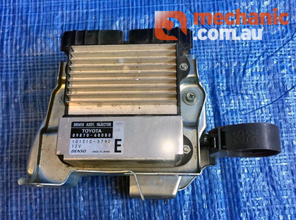
The 1VD-FTV engine fitted to both 70 and 200 Series Landcruisers is a 4.5L Diesel V8 equipped with a Denso Common-Rail Diesel Injection System utilising solenoid-type diesel injectors.
This system is capable of firing the diesel injectors at multiple times per cylinder cycle allowing for pre and post-injections.
In order to allow the solenoid injector to operate at such a rapid rate, the system utilises a high voltage (110vdc) to fire the solenoid injectors. This voltage is generated by the Injector Driver Units and controlled by the Engine Management Computer.

In order to generate this high voltage, the Injector Driver Units consist of a DC-DC converter in order to raise the battery voltage (~12v) to approximately 110v.
The diesel injector solenoids consist of low-resistance (approximately 1 ohm) windings. Paired with the high voltage generated by the Injector Driver Unit, this delivers a significant amount of current allowing the diesel injector nozzles to open in under 1ms.
This high-voltage burst is only required to rapidly open the diesel injector. As soon as the injector nozzile is open, the voltage at the injector reduces significantly during the injection window. Once it is time for the diesel injector to close, voltage is dropped completely which allows the injector to close.
To prevent the diesel injector solenoids from burning out due to the high current, the Injector Driver Unit also houses special current control circuitry and field effect transistors as well as a heatsink in order to dissipate the heat generated.
Caution: There is no established safe method of testing the high voltage side of this diesel injection system. Do not attempt to back probe or measure the high-voltage components of this system.
In the instance of the 1VD-FTV engines, 2 Injector Driver Units are required in order to fire the 8 cylinders as each Injector Driver Unit is only capable of firing 4 diesel injectors.
Each of the Injector Driver Units is powered via a separate relay located in the Engine Bay Fuse Box.
Fault codes that may be observed during fault diagnosis of this system are:
Important note: Both Injector Driver Units are utilised for each bank
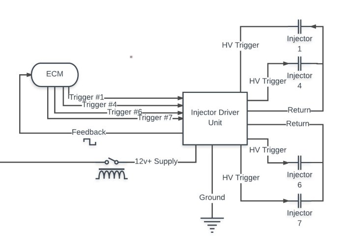
Injector Driver Unit 1 controls cylinders = 1,4,6,7
Injector Driver Unit 2 controls cylinders = 2,3,5,8
In order to fire the Injectors, the Engine Management Computer switches a 5v signal to the Injector Driver Unit. Each cylinder has a respective wire as shown in the diagram below.

In order to collect feedback from the Injector Driver Unit, the Engine Management Computer monitors a 2v signal from the Injector Driver Unit that reports the injection events over a single wire. When observed on an oscilloscope, this signal should mimic the inverse pattern of the control signals (When a control signal is at it’s upper peak, the feedback signal will be opposing.)

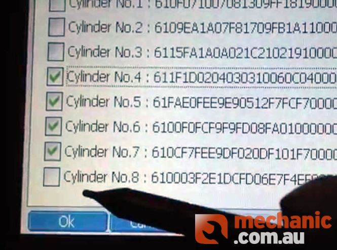
The diesel injectors fitted to this system each carry a unique 30-digit calibration code that is generally etched at the top of the diesel injector.
If the calibration code that is inputted to the Engine Management Computer does not match that of the injector fitted to that cylinder, the diesel injection quantity will be incorrect and this may result in engine damage.
This applies not only to the introduction of a new diesel injector to a system but swapping injectors between cylinders aswell.
In the event you are introducing a new diesel injector to a system, the 30-digit calibration code must be programmed into the Engine Management Computer.

In the event you are required to replace a faulty Engine Management Computer, if possible you will need to access and copy down/sve the 30-digit calibration codes for each cylinder and upload them to the new Engine Management Computer. Otherwise you will need to visually inspect and copy down the calibration codes from each diesel injector. Following this, you will also need to initialise the high pressure pump and carry out the pilot quantity learning procedure using a suitable diagnostic tool.