
We have all seen spark plugs that produce weak sparks like the one shown above, which may or may not produce a misfire that is serious enough to set a misfire code. If the weak spark does produce a trouble code the root cause is usually relatively easy to diagnose and fix, but in some cases, the misfire might not produce a trouble code, even though it is obvious that the engine is misfiring. In this article, we will take a closer look at misfire detection systems, why some misfires do not produce trouble codes, and discuss a new way of determining which cylinder(s) is/are misfiring if no misfire codes are present. Let us start with asking -
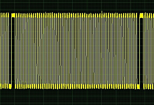
Image source: https://www.searchautoparts.com/sites/default/files/images/Figure%203_21.jpg
The above example of a digital voltage waveform shows the output from the crankshaft position sensor on an engine in which all the cylinders contribute equally to maintaining the crankshaft's rotational speed. In this example, the engine is running at a constant speed and the two “gaps” in the waveform represent a misfire one cylinder.
We have all seen misfires in such waveforms, but while a deviation from a waveform such as this is clear proof of a misfire, waveforms like this provide no information on which cylinder is misfiring, which is the first thing we need to know when no misfire codes have been set. So how do modern OBD II systems detect misfires, and how does it happen that we can often see or hear evidence of a misfire, but no misfire codes are set and stored? Let us look at this in some detail, starting with-
Emissions regulations dictate that all engine misfire detection systems both monitor and regulate two major effects of misfires. The first is that all detection systems must be able to detect whether or not a misfire will increase emissions by more than 1.5% above the level set by the Federal Test Procedure (FTP) standards, and the second is that all misfire detection systems must relate detected misfire rates to the temperature of the catalytic converter. This last point is particularly important because misfire rates have different effects on catalytic converter temperatures under different operating conditions.
For example, let us say that the effective (or operating) temperature of the catalytic converter on a given vehicle is set not to exceed 980 degrees Celsius to prevent damage from occurring to the core. Now let us say that this vehicle develops a misfire rate of say, 5%- if no codes are set, it is almost certainly because the misfire detection system does not regard the misfire as serious enough to raise emissions levels by more than 1.5% of the FTP standards that apply to that particular engine.
If the engine speed is kept low, it is unlikely that the catalytic converter’s core will overheat. However, if the engine speed rises to say 5 000 RPM, and is kept at that level over an extended period, the catalytic converter will almost certainly overheat even though emissions may not increase by more than 1.5% of the applicable FTP standards for that engine.
This is where things get difficult though: under these conditions, emissions will certainly rise by more than the level allowed by the FTP standards, but not primarily as the result of the misfire. Emissions will rise because of a decrease in the efficiency of the catalytic converter caused by the overheating of the converter's core- at which point the question of which cylinder(s) is/are misfiring becomes moot.
Given the above, it would be fair to say that for the purposes of exhaust emission control, the FTP standards that regulate the relationship between a misfire rate and the catalytic converter temperature for any particular engine take precedence over how the OBD II system on that engine detects misfires. Note however that this is not the same as saying that knowing how misfire detection systems work is not important. Quite the opposite is true because we need to know how these systems work if we are to understand the relationship between the causes and effects of misfires, and how that relationship ultimately affects catalytic converter operation. So let us discuss some specifics of-
OEM manufacturers currently use one of three methods to detect misfires, and while all three methods are reasonably accurate, all three methods also have significant drawbacks that reduce their accuracy at high engine speeds. Nonetheless, the specifics of each method are described below-
Ignition Ion Density
This method uses the resistance of the detonation flame in the spark plug gap to determine how well, or otherwise, the air/fuel mixture is combusting. In practice, a second high-energy current is passed across the spark plug gap after the ignition spark had been delivered, which ionizes the gases between the spark plug electrodes. A dedicated detection circuit analyses the resistance the second spark had encountered in the space between the electrodes, which yields data on the duration of the combustion event, engine knocking, an approximation of the air/fuel ratio at the time of detonation, as well as evidence of the spark plug’s condition and possible premature ignition.
The misfire detection system identifies misfires based on this data, but since the system is expensive, complex, and difficult to calibrate, it is currently in use on only a few high-end supercars and luxury vehicles.
In-cylinder pressure transducers
While the use of in-cylinder pressure transducers is known to work well, the various underlying technologies are largely still under development and may only be widely available in the next generation of engines that use extremely high compression ratios and ultra-lean fuel mixtures.
In practice though, this system obtains cylinder pressures in almost real-time via the in-cylinder transducers, which data is then compared to pre-programmed lookup tables. Depending on, among other operating parameters, the engine speed, engine load, and cylinder head temperature, the system will determine whether (or not) a misfire is present based on the observed deviation between the actual and desired in-cylinder pressures at different points in the engine cycle.
Measuring crankshaft speed
This system is the most widely used method to detect misfires, and while it works reasonably well, it only works well at relatively low engine speeds.
At the risk of repeating ourselves, let us consider this image again-
Image source: https://www.searchautoparts.com/sites/default/files/images/Figure%203_21.jpg
We need not rehash the basics of crankshaft speed-based misfire detection systems here: suffice it to say though that the waveform above shows a crankshaft that is rotating at a steady speed. However, the information contained in this waveform is limited in the sense that it more properly represents the regular output voltages of the crankshaft position sensor, as opposed to representing the rotational speed of the crankshaft, which is both assumed and inferred based on the regular horizontal spacing of the wave peaks.
While breaks in the spacing of the wave peaks in this waveform might be taken as evidence of a misfire, this evidence is not based primarily on changes in the crankshaft's speed. For instance, wider spacing between the wave peaks that occur at regular intervals could be the result of factors such as broken or missing teeth on the tone ring/reluctor wheel that prevents the generation of a signal voltage at the point of the missing or broken tooth.
As a practical matter, a signal interruption might very well produce a misfire, which will, in turn, produce a variation in the crankshaft's rotational speed but it will be very difficult, if not impossible to infer the degree of such a deviation from a waveform such as this one. As a rule of thumb, misfire detection systems will only report deviations in crankshaft speed that exceed about 2% of the crankshaft speed as misfires or cylinder power contribution imbalances, which means one of two things-
1) If the engine speed is high enough, the rotational energy stored in the crankshaft and flywheel and clutch/torque converter assembly may be high enough to damp out or absorb the momentary deviation in the crankshaft's rotational speed, meaning that the misfire will go unreported, if not undetected
2) The more cylinders an engine has, the more difficult it becomes to detect small variations in the crankshaft's rotational speed because the higher number of cylinders in say a V10 engine, translates directly into an improved inherent engine balance over the inherent balance of say, a four-cylinder engine.
Because of both points 1 and 2, it is extremely difficult to calibrate crankshaft speed-based misfire detection systems to detect misfires at engine speeds much above idling speed. For instance, since the typical duration of each stroke in an engine that runs at 6 000 RPM is only about 5 milliseconds, it is easy to see how misfires that produce crankshaft velocity changes of less than 2% can go undetected even at moderate engine speeds because of the limited time available for signal generation and processing. This is true even on four-cylinder engines, on which a torque input (or loss of torque) from any given cylinder on the crankshaft occurs at a large angular distance from the next torque input/loss.
As a practical matter, misfire detection on vehicles with crankshaft speed-based detection systems is as much a function of catalytic converter temperature as it is of variations in crankshaft speed. However, since a) the catalytic core's temperature can increase to damaging levels through causes other than misfires, and b), fuel injectors are (typically) only disabled when misfires are detected and reported, a new way to detect misfires has become necessary.
This is to ensure that modern vehicles both remain compliant with current emissions regulations, and to eliminate false positives resulting from issues such as flapping drive belts and defective belt tensioners that have the potential to produce crankshaft speed fluctuations- which in some cases, can be severe enough to set false misfire codes, which begs this question-
There is indeed another way, but to explain how it works we have to consider this image one more time-
Image source: https://www.searchautoparts.com/sites/default/files/images/Figure%203_21.jpg
This image shows a waveform obtained from the crankshaft position sensor and an ignition circuit, and in this example, the data is raw in the sense that no filtering mechanism is being applied to it. As stated elsewhere, it is virtually impossible to a) infer changes in the crankshaft’s rotational speed from this waveform, and b), to determine which cylinder is misfiring, so one manufacturer of diagnostic equipment has developed an algorithm that can extract information on the crankshaft’s rotation from waveforms such as the one above. To understand how it works, consider the image below-
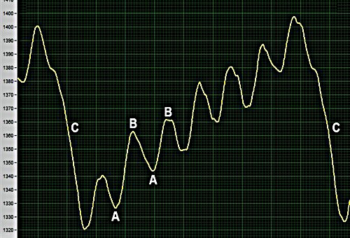
Image source: https://www.searchautoparts.com/sites/default/files/images/Figure%204_20.jpg
This waveform is the same as the one above, but with a proprietary algorithm being applied to it. Here’s what the labels mean-
Note though that while this waveform is an accurate depiction of fluctuations in the crankshaft's rotational speed, it still does not reveal which cylinder is producing the fluctuations. To determine the actual misfiring cylinder, we need to add a second trigger or synching signal, which can be obtained either from any ignition coil on a petrol engine or from any fuel injector on a common rail diesel engine. Adding the second signal will produce a display like the one shown below-
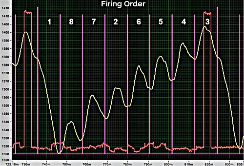
Image source: https://www.searchautoparts.com/sites/default/files/images/Figure%205_15.jpg
In this display, the crankshaft speed signal is superimposed on an ignition trigger signal from an ignition coil, which places the crankshaft speed signal in the context of successive ignition events. However, the oscilloscope that this waveform was produced on can also divide the crankshaft speed signal into the number of cylinders on the engine, and insert the engines' firing order into the divisions.
In this example, the eight cylinders are displayed in their firing order, which reveals that the sharp drop off in crankshaft speed (labelled “C” in the previous image) occurred because of a misfire in cylinder #1. However, it should be noted that the misfire displayed in these waveforms were severe enough to set trouble codes, hence the large observed variations in the crankshaft’s speed.
In practice though, these types of waveforms are analysed on both the rising and falling ramps. For instance, it is the relationship between the amplitudes of rising and falling ramps that determines whether the air/fuel mixture combusted only partially, or not at all. This means that even though this filtering algorithm makes it possible to see which cylinder is misfiring, the learning curve involved in interpreting these waveforms correctly for misfires that do not set trouble codes is rather steep because the rising and falling ramps may not always be as acute as they are in this example.
Additionally, this misfire detection algorithm only works well at low to moderate engine speeds because it is subject to the same limiting factors that prevent other types of misfire detection systems from working well and/or accurately at high engine speeds, which leaves us with this-
Despite its limitations at high engine speeds, this new way of looking at misfires represents a huge development in diagnostics because it allows us to monitor small variations in crankshaft speeds in real-time, which is something no other misfire detection system can do.
Sadly, though, this filtering software is not compatible with all oscilloscopes, meaning that to access it, one has to purchase an oscilloscope and matching software from the inventors of the software, but considering the many hours of diagnostic time this algorithm can save us, investing in a new oscilloscope might not be a bad idea.
