What if one sunny day, the resident auto electrician is not available and you were called upon to diagnose and repair an electrical problem on a customer’s vehicle that involves, say, a melted relay on a customer’s vehicle? Would you be able to diagnose and resolve the problem without reference to a plethora of electrical laws and theorems you can’t remember?
More to the point: does it even matter that you cannot remember half of the electrical theory you were taught in trade school if you specialise in mechanical work, and hardly ever do more complicated electrical work than replace a car battery? This is a difficult question to answer, but if we take the notion that knowledge is power as our point of departure, then having at least a working knowledge of relays and relay-controlled circuits would certainly make it easier to find and repair the problem- even if you are not an expert auto electrician.
Having said that though, bear in mind that although it would be a mistake to underestimate the complexity of some relay-controlled circuits on modern vehicles, the good news is that, for the most part, you (mostly) need neither an exhaustive knowledge of electrical theory nor a box full of fancy test equipment to repair these circuits. So, if you don't do electrical work every day, or very often, this article should provide all the answers you need to repair relay-controlled successfully. Let us start with this question-
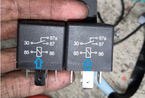
We needn’t spend too much time on this, so this section is more in the form of a brief refresher than a lesson, so here is what the numbers (according to the almost ubiquitous DIN standard) on this pair of relays mean-
On almost all high-quality relays made by reputable manufacturers, these numbers will also be present on the base of the relay close to the actual terminals, which makes it almost impossible to wire a relay incorrectly.
NOTE: Note, though, that electromechanical relays such as the ones shown here come in two “flavours”- Type A, and Type B. While the two types of relays work in the same way, two pins, most often “30” and “86”, are transposed for reasons that are somewhat less than clear. Nonetheless, the practical effect of this variation is that relays are not necessarily interchangeable because the corresponding sockets in the fuse box are wired to accept only type A or type B.
Putting the wrong relay into the wrong fuse box means you could connect battery positive directly to ground if you use the wrong relay, so be sure to check the pin configuration on all new relays before you install them, which brings us to-
While solid-state relays, aka known as "electronic relays" have been in widespread use in industry for at least thirty years, these relays are now fast becoming the preferred norm in automotive use. There are several reasons for this, including the fact that these relays have no moving parts and that they work with extremely low input currents. Perhaps most importantly, solid-state relays have extremely fast switching times; for instance, most solid-state relays now in automotive use energises in about 0.0001 seconds, and deactivate in about 0.000075 seconds if they are properly grounded.
However, while solid-state relays perform the same functions as their electromechanical counterparts, they cannot be used in place of conventional relays without making extensive modifications to the vehicle’s wiring. Here is why-
Although terminals "30" and "78" on solid-state relays still connect to battery power and device input, respectively, terminal “85” must be grounded permanently, while terminal “86” must be switched to ground* to energise the relay and complete the circuit between terminals “30” and “78”. It might sound weird to have two grounds for these relays to work, and while we need not delve into the complexities of this phenomenon, the principal reason why this works involves the differences in potential between the P-type material and N-type material on either side of the electronic “switch” in the relay.
* In most cases, this ground is supplied by a low-side driver in an ECU, but it could also be supplied by super-sensitive pressure switches, most types of temperature switches, or by LED warning lights. In cases where warning lights supply the ground, the relay’s input is connected in parallel with the light.
Nonetheless, in terms of their functionality, solid-state relays are typically controlled by ECUs at frequencies from 1 Hz to about 1000 Hz, and at duty cycles as high as 90 to 100 per cent. These attributes make solid-state relays suitable for use on resistive loads like seat and steering wheel heaters, rear window or mirror defoggers, and auxiliary driving/fog lights that typically (but not always) require pulse width modulated signals.
TIP: Although electromechanical relays are better suited for use on things like starter solenoids, fuel injectors, motors, and horns that create huge and potentially destructive inductive spikes when they are deactivated, some manufacturers have begun to use solid-state relays for these applications. However, to protect the relay against inductive loads, sold state relays in these applications are protected by a diode to block the inductive load from rushing into the relay, and while this strategy is effective, diode failure is a common problem on many aftermarket relays. Therefore, when you encounter repeated or multiple failures of solid-state relays, be sure to test the diode’s operation as a first step in the diagnostic process.
Note though that since this diode is not always incorporated into the body of the relay, finding the right diode to test can be challenging if you don’t have access to reliable service/repair information, which brings us to-

Even in its most complex form, a relay-controlled circuit is no different from any other circuit, including circuits that are controlled by dual open contact* relays.
* Dual contact relays also have five pins or terminals, but unlike “normal” 5-pin relays that have only one set of contacts, dual contact relays have two sets of contacts, both of which are normally open. These relays do not have many applications on standard passenger vehicles, but they are popular among DIY mechanics that often use them to power things like sets of auxiliary driving lights on off-road vehicles that sport multiple driving lights of various kinds.
Regardless of the types of relays on a vehicle, all relay-controlled circuits need the same five things as other circuits do to work, these things being-
So if something like a radiator fan or an A/C compressor, does not work, the fault can only be in one of these components of the circuit, but things are not quite as easy as that. For one thing, relay-controlled circuits are made up of two separate circuits on the one hand, and the relay, which can be thought of as a sort of electrical crossroad, form forms a part of the total load in the circuit/system when it is energised.
So to keep things simple, you can save yourself a lot of time and hassle by "splitting" the system into its component parts, these being the primary and secondary circuits. For the purposes of this article, the primary circuit would be the low-current circuit that serves to energise the coil in the relay, while the secondary circuit would be the high current circuit that feeds battery power to the electrical consumer via the contacts in the relay for as long as the relay coil is energised.
Let us use a practical example of a relay-controlled single-speed radiator fan on an older vehicle without A/C to devise a simple diagnostic strategy, starting with the-
Primary circuit
We know that in this kind of circuit, either terminal “85” or “86’ is connected to ground, but to keep things simple, let us assume that terminal “85” is grounded while terminal “86” is connected to a switchable low current power supply, which would normally be the ignition switch. We also know that (most) radiator fan switches have internal contacts that close* when the coolant reaches a preset temperature; thus, when the contacts in the fan switch close, the switch provides a ground connection which completes the circuit, which then energises the coil in the relay- provided of course, that the ignition is switched on.
*From the early 1990s, this function was largely performed by a control module, but the basic principle remains; the primary circuit must be completed to establish the secondary circuit. Note though that on many late-model vehicles, the primary circuit might also acquire inputs from an ambient air temperature sensor, vehicle speed sensor, and even the throttle position sensor to calculate appropriate radiator cooling fan control strategies.
Secondary circuit
The energized coil creates a strong electromagnetic field that closes the contact points, thereby feeding battery power to the radiator fan. Since one of the radiator fans’ wires is connected to ground, the circuit is completed, so the fan starts, and will continue to run until the ground connection in the primary circuit is broken by the radiator fan switch (or one or more other implicated sensors). Provided, of course, that the fan motor, the relay, and all implicated switches are working as intended. For the most part, these components are fairly reliable, but what do you do if the fan or other electrical consumer does not start or work as expected? Things can get tricky from this point onwards, but here is what we suggest you do-
There is little point in beginning to test wiring for continuity in a random fashion hoping to stumble across the problem, so we suggest that you do at least the following checks to prevent you from falling down a diagnostic rabbit hole. Here is what we suggest you do first-
Run a diagnostic scan
Oftentimes, trouble codes and their definitions will provide valuable clues as to the nature of electrical problems. For instance, terms like “circuit open”, “low input voltage”, “range/performance”, etc. point to wiring issues, as opposed to pointing to parts/component failures. Note that trouble codes in the A/C system can be particularly helpful since defective pressure- and/or temperature switches in many A/C systems can prevent radiator fans from working.
NOTE: At this point, it might be a good idea also to check all fuses and fusible links.
Test the suspect relay
This is easily done by replacing the suspect relay with a known good from the same vehicle, but in some cases, the vehicle may not have a matching relay. So if you don’t own or have access to a relay tester, you can rig up jumper wires to wire the relay outside of the fuse box. The object is to see if the relay delivers a usable current on terminal “78” (or “78a”, as the case may be), but note that this test is only reliable if you load this circuit between terminal “78” (or “78a”, as the case may be), and a suitable ground.
Moreover, the load, such as an old sealed-beam headlight must be comparable to the load the affected electrical consumer places on the circuit; i.e., if the consumer draws, say 25A, the test load must be 25A, or very close to 25A.
Also, make sure to verify that the rated capacity of the relay you are testing matches the load in the circuit. For instance, a relay that is rated at say, 15A will fail in very short order if it is used in a circuit that draws say, 30A. The opposite is also true; a relay that is rated at 30A will likely not work properly (or not at all) if it is used in a circuit that only draws, say, 10A, and the input (control current) is very small. This is because a 30A relay has a bigger coil than a 10A relay, so the control current may be too small to energise the coil.
Check for current at the terminals in the fuse box
If the relay turns out to work, you can use the wiring diagram on the relay as a guide to identifying the terminals in the fuse box that correspond to the numbers on the relay so that you can test the primary circuit and the secondary circuits independently of each other. Here is one way of doing it with a simple test light-
Once you are (absolutely!) sure you know which terminals in the fuse box correspond to terminals “85” and “86” on the relay, test them across both positive and negative by turns to determine which one is connected to ground. Once you have found the ground terminal, the other one must be the switched control current.
In practice, the ground circuit must be intact if the test light lights up when you connect it between the ground terminal in the fuse box and battery positive. Testing the circuit between the switched input terminal in the fuse box and ground is sometimes a little more difficult because this requires figuring out what it is that switches the control current on and off. You may need a wiring diagram or other service information for this, but once you have figured out the switching mechanism, but this circuit must be good if the test light lights up when you connect it between the switched input terminal in the fuse box and battery ground.
You can test the high-current circuits in much the same way. Since terminal "30" is always connected to the battery positive, a test light will light up when you connect it between terminal "30" in the fuse box and a suitable ground; if it does light up, this circuit is good. Note though that on some vehicles this power supply may not always be "hot", meaning that power may be present only under some conditions, such as when the engine cranks. You may need to check or verify this with reliable service information.
Nonetheless, terminal “78” (or “78a”, as the case may be) is always connected to one end of the electrical consumer, while the other end (of the consumer) is connected to ground. Therefore, if you supply battery power to the consumer directly via terminal “78” (or “78a”, as the case may be) in the fuse box and the consumer works, the circuit is good. However, if the consumer, like a fan or blower motor works too slowly, or begins to overheat, the motor may be defective, or it may have a poor connection to ground, which brings us to-
The easiest way to interpret test results is to reduce the problem circuit to its simplest form. We mentioned elsewhere that a relay represents a sort of crossroads that serves to connect different electrical paths. Thus, if you remove the “connection”, you have four* discrete circuits; two that run to ground, one that runs between a terminal and the battery positive, and one that runs between a terminal and the source of a switched low current.
*Note that in some cases, such as in radiator fan circuits, there may be several additional "branch roads/circuits" present, but the basic principle remains the same- removing the relay from the circuit effectively splits the overall circuit into its component parts.
Thus, from a diagnostic perspective, it makes perfect sense to test each section or branch of the overall circuit one section at a time because a) it is easier this way if you do not have access to a wiring diagram and/or specialized test equipment, and b) it is extremely rare for two sections of a relay-controlled circuit to fail at the same time. At the risk of putting too fine a point on it, testing one section of the overall system at a time allows you to exclude some possible causes of the circuit failure definitively. For instance, if the control side of the circuit works, the fault must be in the load side of the circuit, and vice versa, which leaves us with this-
While we realise how uncomfortable it can be to operate outside of our comfort zones, sometimes we have no choice in the matter. So, if this happens to you that you are forced by circumstances to diagnose issues in a relay-controlled circuit, we hope that this article has given you some new and valuable insights into not only how these circuits work, but also into how to approach the problem.
In most cases, there is no need to remove and open wiring harnesses, or at least, not entire harnesses, provided you first reduce the problem to its simplest form, and then take a calm, logical approach that will lead to a resolution of the problem much sooner than you would have thought possible.
