As most of us are not expert-auto-electricians, most of us have l had to decide or determine what is faulty: a relay, or some part of a circuit on either side of a relay. The distinction is not always as clear-cut as we would have liked, since faulty relays can mimic the signs and symptoms of defective circuits, and vice versa, as many of us have discovered some hours into a diagnostic process. Thus, in this article, which is the first in a two-part series we will take a closer look at the relays we encounter daily in terms of how they work, as well as provide some tips on diagnosing circuits that are controlled by relays, in the follow-up article. Let us start with this question-
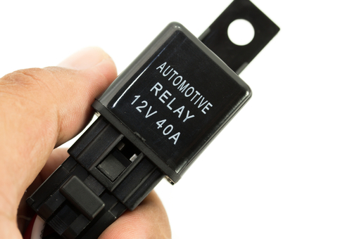
Relays have been in common use since the mid-1940s to control high-amperage starter motor and headlight circuits, so they are not exactly new inventions, and although most relays are now more compact than they were in the 1940s, they still control high-amperage circuits in modern cars.
There are many examples of such circuits on modern cars. Some that come immediately to mind include headlights, A/C compressor clutches, radiator fan motors, tailgate lift motors, interior fan/blower motors, and even sunroof motor drives. These types of circuits typically draw more current than could be handled by delicate switches without damaging them, so control switches are used to energise relays, which then allow high currents to flow to electrical consumers directly from the battery through the relays’ more robust switch, which begs this question-
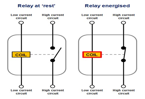
Image source: https://www.12voltplanet.co.uk/user/Simplified_relay_diagram_Lg.png
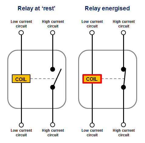
The diagram above illustrates the basic operating principles of a typical 12V electro-mechanical automotive relay. Here is how it works-
The little yellow rectangle in this diagram represents a coil, which consists of a series of copper wire windings around an iron core. This coil turns into an electromagnet when it is energised by a low current when a control switch is turned on. These currents typically measure only a few tenths of an amp, and they very seldom exceed about 0.5 amp, which falls in a range of currents that control modules can handle without suffering damage.
When the coil is energised, it turns into an electromagnet that acts on a moveable contact point to close a circuit, thus acting as a switch in the high-amperage circuit between the battery or other power source and the electrical consumer. When power is removed from the coil, the magnetic field in the coil decays very rapidly, and the moveable contact point returns to its at-rest position under spring tension.
It should be noted though that the collapsing magnetic field can sometimes inject extremely high inductive voltages into the upstream side of the relay's control circuit. This phenomenon is roughly analogous to how ignition coils create ignition sparks in their secondary windings, but since a) relays do not have secondary windings and b), the input currents are very low, induced currents are typically harmless. However, in cases where induced currents flow through control modules, the relay will typically incorporate a resistor or other filtering component such as a diode to neutralise or absorb the current that is induced by the collapsing magnetic field.
In most cases, the relay will be “Normally Open”, meaning that a low-current input is required to energise the coil to close the switch. Nonetheless, “Normally Closed” relays are often used on many applications, but in most of these cases, the “Normally Closed” label applies to one of the contacts or switches in relays that control more than one high-amperage electrical consumer or circuit. We will discuss these types of relays later on, but before we get to that, let us look at-
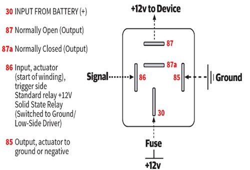
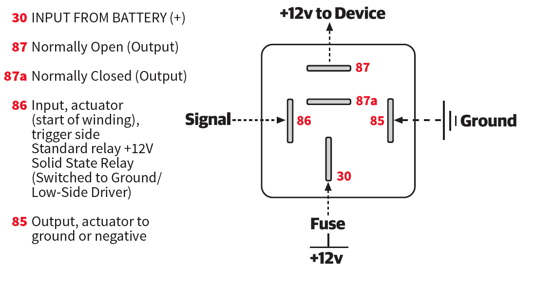
Image source: https://dsportmag.com/wp-content/uploads/2019/05/156-Tech-Relays-002-Diagram.png
This diagram shows the labelling or numbering on the terminals of the two types of relays that are most commonly used in modern vehicles. Note that although this diagram shows five-terminal relays, Type A and Type B relays are also available in the more common four-terminal configuration. However, to keep things simple, let us look at what the terminals' numbers mean as they are shown here, so consider the table below-
So, why are these specific numbers used, you may ask, especially since most of can figure out the purpose(s) of each terminal without necessarily referring to the numbers themselves? If the truth were told, however, many of us have also damaged wiring by getting relay terminal numbers wrong, so to prevent this from happening, almost all car manufacturers across the world have adopted this particular numbering convention that is based on the German DIN 72552 standard.
“DIN” stands for Deutsches Institut für Normung (German Institute for Standards), and the 72552 standard covers the numbering or labelling of a wide range of electrical connections. Some examples include the numbers “15” and “1” on old-style ignition coils, where “15” indicated the B+ input from the ignition switch, and “1” indicated the low voltage connection to the distributor. One other example is starter motors that are labelled “15” to indicate the low current input to the solenoid, and “1”, to indicate the high-current B+ connection to the motor.
However, as far as the terminal numbering on relays is concerned, all terminals on all relays that conform to the DIN 72552 standard* will be numbered in the same way. Thus, all terminals that are labelled #85 will always be the ground connection for the low current input, etc, etc.
* Note that on some British, American, and Asian vehicles made before about 1980, one might still find relays that follow one of several different terminal/terminal numbering conventions that were in use at the time. None of these old-style conventions bore any resemblance to the DIN 72552 standard, and while modern relays can sometimes be used as direct replacements for these old relays, it is always a good idea to check the wiring on older vehicles to verify that individual circuits on the vehicle conform to the numbering convention of new relays.
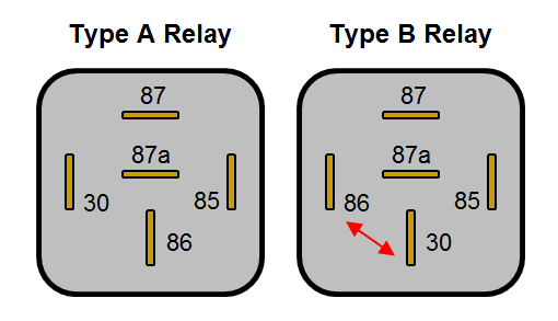
While terminals on modern relays are always numbered in the same way, there are two types of relays in common use today. We have all seen relays with four terminals and others with five terminals, but the main difference between these relays is not about the number of terminals- it is about how two terminals on some five-terminal relays can be transposed to suit a particular circuit’s requirements. Let us start with five-terminal relays known as-
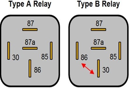
Image source: https://www.12voltplanet.co.uk/user/Type_A_and_type_B_relays.png
Unlike four-terminal relays that are simple make-or-break mechanisms, in the sense that they either simply complete or interrupt circuits, five-terminal relays, also known as “changeover” or Single Pole Double Pole relays, can sometimes be a bit more complicated. These types of relays come in two main terminal configurations, or types, so let us start by looking at-
The image above shows both type A and type B relays, both of which can be used to power two separate circuits, albeit not at the same time. In both types (that also come in microformat) B+ connects to terminal 30, but only one of the high-current outputs (terminal 87 or terminal 87a) will be open, while the other is closed. Regardless of which terminal (87 or 87a) is normally open, the two outputs will switch places both when the relay is energised or de-energised.
One practical example of this type of arrangement concerns headlights that require separate power inputs for the high and low beams, which was a common feature of old-style sealed beam headlights, or even more modern headlights that use replaceable bulbs. Thus, in such a set-up, energising the five-terminal headlight relay by activating the headlights' control switch will pass power directly to the low beams through the normally closed high-current switch in the relay. While it is tempting to think that simply de-energising the relay will cause the normally closed and normally open terminals to swap places thereby passing current to the high beams, things are a bit more complicated than that.
Nonetheless, regardless of the control mechanism, one five-terminal relay can control the high and low beams (or two other circuits) through a single control switch. However, in type B five-terminal relays, the positions of terminal 86 (the low current control input), and terminal 30 (B+) are transposed relative to the positions of the same terminals on Type A relays.
As a practical matter, this makes no difference to how the relay operates, but since the position and layout of the terminals are the same on both types of relay it is possible to insert a type A relay into a socket that is wired for a type B relay. If this happens, the B+ positive circuit will almost instantly destroy the relay’s coil, and quite possibly, large sections of wiring between the ignition switch and the relay, as well. In fact, this writer has seen melted fuse boxes and fused wiring harnesses caused by mechanics that plugged type A relays into type B sockets, so be sure to make a careful visual comparison of the way terminals are numbered when you replace five-terminal relays, which brings us to-
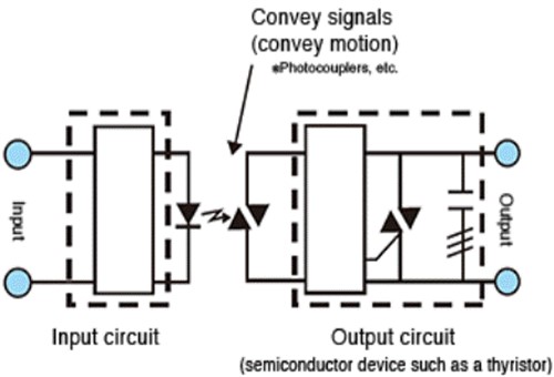
Image source: https://omronfs.omron.com/en_US/solutions/relays/relay-basics/ssr-define-img02.gif
The term "solid-state" as it applies to automotive relays is not so much a misnomer as it is a generic term that covers several distinctly different types of relays used in modern automotive applications.
We need not delve into the different types of solid-state automotive relays here, but suffice to say that from our perspective as technicians, solid-state relays are relays that contain no moving parts. In practice, many high-end vehicles are now using increasingly higher numbers of solid-state relays because of the distinct advantages that this type of relay has over electromechanical relays, which we will list a bit later on.
Before we get to those specifics though, we must explain how solid-state relays work if they have no moving parts. Here is how-
Instead of an electromagnet that pulls a set of contacts closed against spring tension, a solid-state relay turns the low current input, which can be either AC or DC, into a light signal/pulse with an LED. The light pulse is then transmitted through a small, but permanently open air space in the body of the relay called an “opto-isolator”, and having passed through the air gap, some complex electronic components then convert the light signal back into an electrical signal, which has the effect of "closing" an electronic switch to connect the battery current to a load.
As a practical matter, the switching time of a solid relay is near-instantaneous, and since no moving parts are involved in the switching process, solid-state relays operate silently meaning that not hearing the “clicking” sound does not necessarily mean that the relay is not working. In these cases, you need to perform targeted pinpoint tests on both the relay and the relevant wiring to verify that the relay is working or not, as the case may be.
From a diagnostic perspective, this is an important aspect of solid-state relays to keep in mind, since it may not always be clear the if relays in standard ISO 7588 sockets* are of the solid-state or electromechanical variety.
* The standard that describes the dimensions and configurations of the relay sockets on almost all vehicles that are produced today.
Nonetheless, some of the advantages of solid-state relays in automotive applications include-
Note though that while electromechanical relays are generally immune to voltage spikes on their normally open sides, non-OEM or non-OEM equivalent solid-state relays in some applications can sometimes be “triggered” by voltage spikes. Therefore, when you are dealing with erratic or sporadic electrical issues, be sure to check that a) the solid-state relays that might be installed are OEM-equivalent, and b), that the voltage supply to the affected systems/components is stable and within prescribed limits/thresholds.
However, resist the temptation to replace solid-state relays with electromechanical relays in an attempt to isolate erratic or sporadic electrical issues. The problem with this approach is that electromechanical relays require higher control inputs to work than solid state relays do, meaning that even if your control input is within specifications, it will almost certainly not be strong enough to trigger an electromechanical relay, thus complicating your diagnostic process, which leaves us with this-
We hope that this guide has given you some new insights into the subject of automotive relays. In the next article, we will discuss some diagnostic tips and tricks that non-expert auto-electricians can follow to make it easier to decide if an electrical problem involves a relay malfunction or a circuit failure. This distinction is not always easy to discern, but once you understand how relays work and what role(s) they perform in the management of electrical systems and circuits, it becomes a whole lot easier to trace electrical faults and failures.
