In Part 1 of this series of articles, we discussed relays in terms of how they work and what they do. In this instalment, we discuss some easy-to-follow steps to diagnose not only relay-controlled circuits but also how to test and diagnose defective relays, themselves. Let us start with-
This writer had often seen non-electricians faltering over basic electrical diagnostics because many mechanics seem to forget the fundamentals of electrical circuits when they deal with relays and relay-controlled circuits. In their defence though, it must be stated that it is easy to overthink problems and their possible causes and solutions when one does not do electrical diagnostics every day.
Nonetheless, since we can all benefit from the “KIS” (Keep It Simple) principle, it will help to bear in mind that electrical circuits typically need five things to work, these five things being-
There is an exception to this though. Circuits that control consumers with high-amperage current requirements need an additional component to work. This component is typically a relay that functions as a secondary control mechanism to protect delicate control switches and primary controls, such as driver circuits in control modules.
Thus, circuits that incorporate relays can be said to consist of two parts; a primary low current circuit, and a secondary, high current circuit that typically connect high-current consumers directly with a power source through a switch in the relay. Therefore, relays do not only represent a sort of crossroads in some circuits- but they are by virtue of their function, also part of both the circuit and the load.
So if we follow sound diagnostic principles and reduce a typical relay-controlled circuit to its simplest form, we can break the circuit down to its parts, the first of which is the-
Low current section
This section of a circuit is usually the most complex. In some cases, the power input may come directly from the battery to a control switch through a fuse, while in other cases, the power input may pass through the ignition switch and several other components and/or control modules before reaching the control switch through a fuse or fusible link.
Regardless of the power input's path before the control switch though, from the control switch, the current will pass to the relay to activate an internal switch to activate the-
High current section
This section of the current typically connects the electrical consumer directly to the power source via the relay’s internal switch, meaning that this part of relay-controlled circuits are typically relatively straightforward to both trace and diagnose. Bear in mind though that in some cases, both the low and high-current circuits may be protected by a single fuse, while in other cases, the high and low current circuits may each be protected by a dedicated fuse.
How any particular relay-controlled circuit is protected is not always easy to determine from tracing wiring, so the best way to approach this kind of issue is to consult a proper wiring diagram for the affected application or circuit, which brings us to the question of-
Now that we understand the basic structure of relay-controlled circuits, where do we begin to figure out why the load (blower motor, fog light, or sunroof, etc,) is not working? We could, of course, replace the suspect relay with another (apparently) identical relay from elsewhere in the fuse box, but that is often a poor choice because even if the consumer now works, it does not necessarily mean that the suspect relay was, in fact, defective. Relays are deceptively similar; they may look the same from the outside, but in practice, they are often calibrated differently, meaning that while a relay from elsewhere in the fuse box may power the ultimate load, the replacement relay may overheat from an excessive current.
To avoid damaging perfectly good relays, we suggest that a better way to approach a suspect relay is to begin by measuring the current in the primary (low current) side of the circuit. To do this, you need to identify the suspect relay’s control mechanism, and then to trace the relay’s two power inputs back to the power source, which is typically the battery.
One power input will be the relay’s low-current control input, and the other will be the high-current input that connects the battery directly to the electrical consumer via the relay’s internal switch. Tracing wiring is sometimes much more easily said than done, but if you follow the wiring schematic carefully, you will eventually reach a fuse*, which is the first point at which you need to measure current flow through the circuit.
*For the purposes of this article, we will assume that both parts of the circuit are protected by a single fuse. Note though that if the fuse is blown, do not replace it until you have verified that there are no short circuits in the circuit.
Next, remove the fuse and replace it with an appropriately fused jumper wire, before switching the circuit on. Place low amperage current clamp around the fused jumper wire and observe the reading. Note that the current in this circuit will typically be only a few tenths of an amp, with a maximum of about 0.5 amp: if you see such a current, but the ultimate electrical consumer was not working, the relay may well be defective, but resist the temptation to condemn the relay out of hand, just yet.
If you see a zero reading on the current probe, it means that no current is present in the circuit, and therefore, the relay will not be energised. In this case, the easiest way to find the problem is to perform voltage drop tests on the low-current circuit back to the battery, paying special attention to continuity across intervening splice joints, connectors, and control switches.
Assuming, however, that you do see an appropriate current reading on your amp probe, we suggest that instead of cannibalising the fuse box for a replacement relay, you repeat this measurement at the relay socket by-
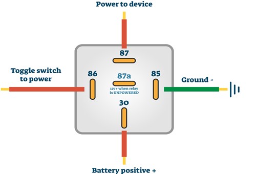
In the previous article, we discussed the German DIN 72552 standard that determines the current relay terminal numbering convention, as shown in the above image. It is extremely unlikely that you will encounter a different numbering convention in a post-1980's vehicle, so refer to this schematic when you are ready to measure currents at the suspect relay's socket.
Thus, assuming that you found an appropriate current reading at the fuse in the primary circuit, remove the suspect relay from its socket, and insert an appropriately fused jumper wire across the terminals in the socket that corresponds to terminals 86 and 85 (on the relay) to complete the primary circuit. If you energise the circuit and you see the same current reading across these two terminals (86 & 85) that you saw at the fuse, the primary circuit is intact. If however, you saw an appropriate reading at the fuse but there is no current at the relay socket, you have an open circuit between the fuse and the relay socket.
The next step is to bridge the terminals that correspond with terminals 30 and 87 with an appropriately fused jumping wire, but bear in mind that terminal 30 is always connected directly to B+, so take care to not cause short circuits when you bridge these two terminals in the relay socket. Note that if the secondary circuit is intact, and the consumer itself is in good working condition, the consumer will start working when you bridge terminals 30 & 87 since the jumping wire is replacing the relay. Nonetheless, if the consumer works and you have an appropriate current flow throughout the primary circuit, you can safely regard the suspect relay as defective.
Note, however, that if bridging terminals 30 & 87 does not make the electrical consumer work, the safest thing to do is to connect a scan tool to the vehicle to check for any trouble codes relating to the affected circuit. Codes relating to short circuits will manifest as discoloured, burnt, and/or overheating wiring* in the secondary circuit, while open circuits can be pinpointed by performing voltage drop tests between the battery and the affected electrical consumer, paying special attention to continuity across slip joints, and connectors, as well as the integrity of ground connections.
* A thermal imaging device can save you hours of diagnostic time; simply point it at the relevant harnesses and the sites of trouble spots will immediately become apparent as they warm up.
TIP #1: If bridging terminals 30 & 87 makes the electrical consumer work, take a current reading from the fused jumping wire while it (the consumer) is in operation. If your scan tool has suitable and relevant bidirectional controls, you can also activate or cycle the consumer repeatedly to verify that the consumer does not draw more (or less) current than specifications allow. This is an important point because both marginal over and under current conditions can damage the electrical contacts in electromechanical relays over time.
Thus, while merely replacing the relay with a new one might seem to resolve the problem, replacing the relay without verifying that the consumer is drawing the correct current might cause the replacement relay to fail as well, which brings us to-
In practical terms, relays can be thought of as solenoids, but instead of acting on a movable valve shuttle or pintle, a relay coil moves an electrical contact. In practice, relays are wired to use a low current input to control a high-current output circuit, and as a result, relays have at least two circuits. Moreover, since relays have at least two circuits, relays can fail in at least two ways, these ways being-
Determining how a relay might have failed is, however, not difficult, and while specialised (and expensive) tools such as relay emulators can make the job easier, it is possible to test relays reliably with nothing more than a digital multimeter. Consider the image below-
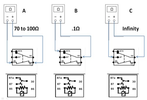
This diagram illustrates the terminals on relays you need to connect with a multimeter to perform basic tests for resistance and continuity. Let us look at these tests in some detail-
Relay coil tests
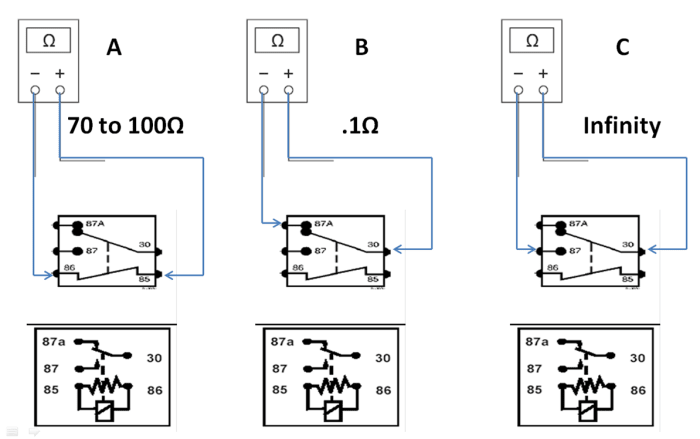
Depending on the relay terminal numbering scheme, test the coil between terminals 85 and 86 (or between terminals 1 & 2) using the resistance (Ohm) setting on the multimeter. Here is what you should see-
TIP: While relays typically build up some temperature during normal use, and especially during high duty cycles, no relay should ever get hotter than about 40oC or so during normal use. If you encounter higher temperatures than this, the root cause of the excessive temperature is more likely to be an abnormally high current draw by the electrical consumer than a fault with the relay, which brings us to-
While relays offer electrical engineers a cheap and effective method of controlling high-current circuits with low-current inputs generated by microprocessors, relays can “inject” voltages that could be as high as 300V AC into DC circuits when the magnetic fields in relay coils collapse.
This is a normal function of electromagnets, but since induced voltage spikes can destroy not only delicate circuits in microprocessors but also light-duty switches and wiring, some relays incorporate either a diode or a resistor to absorb the voltage spikes that are induced by collapsing magnetic fields around relay coils.
To prevent this kind of damage, many relays feature a diode or a resistor that is connected across the two terminals leading into the relay coil. Let us look at how these components work in practice, starting with-
Clamping diodes
Since diodes are analogous to one-way check valves, in the sense that they only allow current to flow through them in one direction, a diode in a relay is connected with its positive pole to the ground side of the control input, and its negative pole to the power side, which might appear to be counterintuitive.
However, the fact is that the polarity of an induced current is reversed relative to the original input, so when a magnetic field in the relay collapses, the diode's connections are aligned with the induced voltage spike, which allows the induced spike to flow back into the relay's coil, where it is dissipated without flowing into the vehicle's electrical system.
Clamping resistors
Clamping resistors used in this application are non-directional, which means that there is always a minute current flowing through these resistors when the relay is energised. However, when the magnetic field around the coil collapses, the resistor absorbs the spike by converting the current into heat, instead of channelling the spike back into the relay’s coil.
NOTE: One sure sign of a bad or failing clamping diode or resistor is "popping" or "crackling" sounds coming from the vehicle's audio system. This is particularly noticeable when the A/C system is deactivated because the bad or failing clamping diode or resistor is failing to isolate or contain the collapsing magnetic field in the A/C clutch's control relay.
While this article does not pretend to be the last word spoken on relay-controlled circuits, we hope that the information presented here has given you some new and usable information not only on how relays work but also on what to look for when diagnosing circuits that are controlled by relays.
Even the most advanced automotive relays are at their cores, just simple switching devices that control high-current circuits with low-current inputs, and once you understand their function, you remove the mystery and guesswork around how these kinds of circuits work. Thus, once you see relays as nothing more than simple switching devices, the root causes of many types of circuit failures will jump out at you.
