The battle against excessive exhaust emissions really started in 1967 with the introduction of positive crankcase ventilation systems and although this innovation was reasonably successful, rapid changes to emissions regulations soon required much more effective measures to curb urban smog and damage to the environment. One such measure was the use of a blower fan to introduce excess air into the exhaust stream at its hottest point as a means to help oxidise excessive amounts of hydrocarbons, and while this also worked reasonably well, developments in combustion chamber design and improved fuel injection methods/strategies soon obviated the need for air pumps and excess oxygen.
Now however, the air pump is back and in this article, we will discuss the reasons for its reintroduction, as well as some of the common problems you are likely to encounter on vehicles of mainly European manufacture that are equipped with secondary air injection systems, starting with this question-

While catalytic converters promised the huge reductions in exhaust emissions required by ever more-stringent emissions regulations, the newly developed catalytic converters only started to work when they reached their effective operating temperatures. In the early 1990’s, this could take up to several minutes because at this time, there was insufficient oxygen in the average vehicle’s exhaust stream to oxidise hydrocarbons and other exhaust components effectively.
As a practical matter, long catalytic converter warm-up times translated into large volumes of unconverted exhaust emissions being released into the atmosphere during the relatively long time it took for the exhaust stream to warm up a catalytic converter to the point where it started neutralising harmful exhaust emissions. Thus, to reduce warm-up times, almost all vehicle manufacturers reverted to using a dedicated air pump to deliver excess atmospheric air to catalytic converters at a point just before the upstream oxygen sensor or in some designs, to each exhaust port directly.
In addition to the oxygen an air injection pump delivers to a catalytic converter, the ECU may also increase the injector pulse width to enrich the air fuel mixture, and/or advance the ignition timing. The combination of additional air and fuel has the effect of raising the exhaust gas temperature to 600+ degrees Celsius within a few seconds, which means that in practice, most catalytic converters on modern vehicles with secondary air injection systems start to work in a matter of seconds, as opposed to several minutes. Note though that in some instances, such as during very low ambient temperature conditions, it can take as long as two minutes for a catalytic converter to reach its effective operating temperature.
In terms of operating principles, the ECU will generally keep the secondary air injection pump running while making appropriate adaptations to fuel delivery and ignition timing only until it senses that the catalytic converter is converting exhaust gas, based on input data it receives from upstream and downstream oxygen sensors. In some cases though, the ECU may keep the air injection pump running for a few seconds after the catalytic converter has started the conversion process; however, in these cases, injector pulse widths and ignition timing settings will usually revert to closed loop operation values to protect the catalytic converter against possible overheating, which brings us to-
Although secondary air injection systems are generally very simple and uncomplicated, almost all systems are prone to failures and malfunctions that are largely similar across all applications. Common failures and malfunctions could include one or more of the following-
Air pump failure
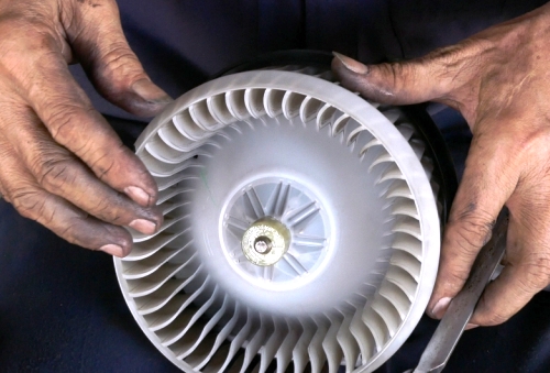
While air pump failures do occur, it should be noted that pump failures are almost always caused by corrosion that derives from water or moisture in exhaust gas that finds its way into the pump enclosure. In very cold climates, freezing temperatures can freeze water that may have collected in the pump enclosure, which can cause pump motors to burn out, but since freezing temperatures very rarely (if ever) occur in Australia, water that does collect in the air pump more commonly causes the pump impeller to corrode.
The most common symptoms of a corroded air pump impeller could include-
Combination valve failure
The term “combination valve” derives from older iterations of secondary air injection systems in which the valve through which secondary air passed into the exhaust system was also used as a vent valve. In vent mode, the valve was effective in preventing backfiring though the exhaust, and while modern systems do not have a vent function, the term “combination valve” is still in common use in almost all markets.
Nonetheless, modern combination valves can be either vacuum operated through a vacuum actuator, or electronically controlled by a dedicated control solenoid that can be either pulse-width modulated, or a simple on/off direct acting unit, depending on the application.
As a practical matter, the normally closed combination valve separates the air injection pump from the exhaust system. However, the combination valve is usually connected to the exhaust system with a hose or steel pipe, and while the valve itself is therefore not subjected to the high-temperature exhaust gas, exhaust gas that remains in the hose or pipe cools down considerably after the system shuts down. The drop in temperature causes water in the exhaust gas to condense when the system shuts down, and some of this water almost always collects at one or more points in the hose or pipe.
Over time, the dissolved acids (present in exhaust gas) in the accumulated water damage the valve seat and leaks into the pump through the corroded valve seat, which is what then causes pump impellers to corrode. In addition to water, carbon can also collect in the connecting tube, and in severe cases, carbon can build up to the point where the combination valve becomes clogged or stuck in the closed position.
It should be noted though that both water seepage into the pump through the combination valve, and excessive carbon deposits in the valve itself and/or connecting tube will trigger the same generic fault code(s), P0410 – Secondary Air Injection System, and P0411 – Secondary Air Injection System Incorrect Flow Detected, depending on the nature of the problem. On V-type engines that have two combination valves, generic codes P0491 and/or P0492 may also be present, the latter codes referring to the affected bank of cylinders.
On most applications, the ECU uses input data from the oxygen sensors to deduce the volume of secondary air being injected. For instance, if the catalytic converter enters closed loop operation within a specified time, the ECU deduces that sufficient secondary air is present. Conversely, if the catalytic converters’ warm-up time exceeds a specified maximum amount of time, the ECU will deduce that insufficient secondary air is present (based on the similarities between the signal voltages of the upstream and downstream oxygen sensors), and it will set an appropriate fault code as a result.
However, on some applications, the volume of secondary air is measured by the MAF sensor, or in some cases, most notably some BMW models with the M54 engine, secondary airflow is measured by a dedicated secondary air injection system MAF sensor. On these applications, common MAF sensor issues such as dirty or contaminated sensing elements, or resistance/continuity issues in the MAF sensor’s control/signal circuit must be considered as possible causes of codes P0410 and/or P0411 before an air injection pump or valve is condemned out of hand.
It is particularly important to note that the combination valve itself must be tested before any conclusions can be drawn about the most likely cause(s) of secondary air injection system related fault codes. On vacuum operated designs, the vacuum actuator’s diaphragm must be checked with a hand-held vacuum pump to verify the integrity of the diaphragm. At the same time, the valve must be inspected to see if the valve seat actually responds to inputs from the actuator, as well as to verify that the valve seat closes positively when vacuum is removed so as not to allow exhaust gas to enter the pump.
Similarly, the operation of the control solenoid must be verified, either by applying current to it directly, or by commanding the valve to cycle open and closed with a suitable scan tool. Regardless of the valve design though, it should not be possible to blow through it against the closed valve; if any air passes through the valve (however slowly) when it is in the closed position it is defective, and must be replaced.
Damaged hoses
Given the fact that secondary air injection discharge hoses are subjected to both high under-bonnet temperatures and continual chemical attack by oil and fuel vapours, it is not surprising that a large percentage of system failures are caused by split, hardened, or cracked hoses.
However, inspecting this hose properly almost always requires the complete removal of the hose, which often causes the hose to split, break, or fracture, especially on high mileage vehicles. Therefore, it is always a good idea to inform your customer of this fact, and to quote for a hose replacement whenever you encounter secondary air injection issues on older vehicles.
Damaged vacuum lines
Cracked, split, degraded, or perished vacuum lines is a common cause of system failures on vacuum operated combination valves. Note that on some Volvo models, this hose is often kinked or pinched during assembly in the factory, so be on the lookout for restrictions and/or kinks in this, or any other vacuum line in the secondary air injection system.
Note that even partially restricted vacuum lines could prevent the combination valve from opening fully, which will eventually set insufficient secondary airflow codes.
Blown fuses/defective relays and/or solenoids
Secondary air injection pumps are invariably fed with power through a relay that is controlled by the ECU; with the relay feed circuit being protected by a fuse or fusible link. Moreover, the control circuit often contains load-sensing circuits that the ECU uses both to monitor the operation of the combination valve solenoid, and to check for shorts to ground.
Issues in these circuits will generally set generic codes P0412 to P0419, while issues in the relay driver and pump motor circuits will usually set one or more manufacturer specific codes, which brings us to-
While scan tools are of some use in diagnosing secondary air injection systems because it can be used to activate the air pump remotely, this is about as far as their usefulness goes. In practice, it is often easier to dismantle the entire system regardless of which codes are present, since this allows one to inspect and/or test each component of the system with relative ease.
The problem is (for instance) the fact that a seized or burnt out pump motor is seldom caused by a problem or defect in the pump/motor assembly design. It is far more likely to be caused by a leaking combination valve, which might work perfectly when it is activated manually or with a scan tool. Bear in mind that combination valves are designed to keep out exhaust gasses that are at normal exhaust pressures, meaning that the forces holding the valve closed are very small. It is therefore easy for acid-laden water to create a leak path past the valve seat, which will eventually cause the pump the fail.
The most profitable approach to take when diagnosing secondary air injection issues is to examine the entire system, and to replace any part or component in the system that is in a less than perfect condition. This will not only save you a lot of diagnostic time- it will also save you from the embarrassment of having to explain to your customer why the same codes are again present within a few a days of you having fixed the original problem.
