Despite all the talk about electric vehicles being on the point of taking over the world, the fact is that the internal combustion engine will be with us for a long while yet. Moreover, new technologies to extract more energy from fossil fuels and to reduce exhaust emissions, even more, are being introduced at a dizzying pace.
We don't have to delve into the technical details of all such new technologies here, but as a point of interest, they include ways to mix fuel and air outside of the cylinders, as well as the use of ultra-high compression ratios to combust petrol without ignition sparks. However, one existing technology, known as Displacement on Demand, or Cylinder Deactivation, is now being touted as the best possible way to make large engines more fuel-efficient.
In practice, though, cylinder deactivation is not exactly new, but advances in engine management and control systems have now made it possible to manage these kinds of systems more effectively. Thus, in this article, we will take a closer look at displacement on demand systems on engines with more than four cylinders. Let us start with this question-
As a practical matter, Displacement on Demand is a bit of a misnomer in technical terms, because deactivating some cylinders does not change an engine’s displacement in meaningful ways.
At the risk of being pedantic, it would be more accurate to say that cylinder deactivation amounts to changing cylinder power contributions (on demand) in ways that do not affect an engine’s dynamic balance. For instance, we know that a) unequal cylinder power contributions can set misfire codes, and b), that the longer a crankshaft is, the more it deforms under unequal loads: unequal loads in this case being unequal cylinder power contributions.
In practice, harmonic balancers are designed to absorb and/or damp out crankshaft deformations when all the torque inputs on the crankshaft are equal. However, when some cylinders are deactivated, the torque inputs on the crankshaft become grossly unequal, so unless the misfire detection system is “recalibrated” to ignore imbalances caused by cylinder deactivation, the system will record misfire codes during every engine cycle for as long as cylinder deactivation is in operation.
Therefore, by recalibrating the misfire detection system, it is relatively easy to prevent misfire codes from setting when some cylinders are deactivated. However, recalibrating the misfire detection system does nothing to preserve an engine’s dynamic balance. So how is cylinder deactivation systems implemented in the real world? To explain this, we need to revisit some-
We know that the amount of torque (as opposed to power) an engine develops at any given engine speed is a function of the relationship between its compression ratio, the surface area and the number of its pistons, and the length of the stroke.
While several other things influence an engine's torque output, the above factors are the main factors that determine how much torque an engine produces. However, as a practical matter, only three of the above factors are constant: the stroke length, the number of pistons, and the combined surface area of the pistons. The fourth factor, the compression ratio, is not constant, since cylinder compression pressure is entirely dependent on the throttle opening.
Moreover, when we talk of compression ratios, we need to be sure that we are not confusing static compression with dynamic compression. This distinction is important because it is the difference between static and dynamic compression that largely preserves an engine’s dynamic balance when some cylinders are deactivated.
Nonetheless, let us look at the two different types of compression, starting with-
Static compression ratio
This is merely a simple comparison of volumes within a cylinder when all the valves on that cylinder are closed. In its simplest form, the static compression ratio is the difference between the volume of the cylinder when the piston is at BDC Bottom Dead Centre), and when the piston is at TDC (Top Dead Centre).
Thus, if we assume a leak-proof cylinder, we would have a 10:1 static compression ratio if the cylinder's volume were ten times bigger with the piston at BDC than it is when the piston is at TDC. While this ratio never changes, at least, in theory, its only practical application is to compare standard engines for marketing purposes.
Dynamic compression ratio
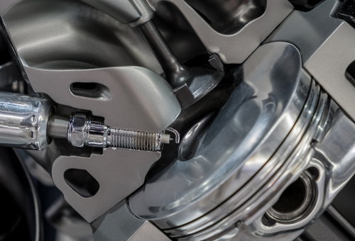
To get a better understanding of how dynamic compression works, and why it is important, consider the image below-
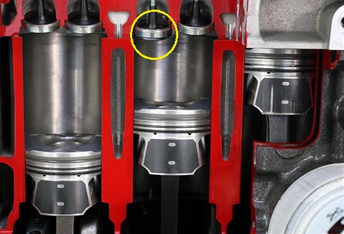
Image source:https://hotrodenginetech.com/wp-content/uploads/2016/02/comp_ratio2.jpg
In his example, the piston on the left is at BDC during its power stroke, and the exhaust valve is just beginning to open.
The piston in the middle is moving upwards, but the intake valve is still open, as shown by the yellow circle. In this condition, air is still moving into the cylinder, and pressure will only begin to build when the intake valve closes. At the risk of putting too fine a point on it, pressure will only begin to build in the cylinder after the-
In an ideal engine design, the intake valve will close at the same moment the air pressure above and below the intake valve seat are equal. However, this rarely happens in practice.
Nonetheless, theory (and many online engine-tuning tutorials) also state that-
Both theory and online tutorials are correct about the first point, but both get the second point wrong. Consider the following two scope traces-
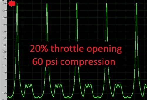
Image source: https://www.vehicleservicepros.com/service-repair/underhood/article/21216014/displacement-on-demand#&gid=1&pid=1
This trace shows the peak dynamic compression pressure on one cylinder of a 5.3L V8 Chevrolet engine. The trace was obtained at cranking speed, with the sparkplug removed, and a pressure transducer installed its place. In this case, the injectors on the engine were also disabled.
Note that with the throttle opening set to a 20% opening with a scan tool, the peak dynamic compression pressure was only 60 psi (413.7 kPa). Now consider the next trace-
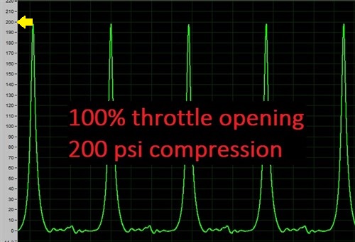
Image source: https://www.vehicleservicepros.com/service-repair/underhood/article/21216014/displacement-on-demand#&gid=1&pid=2
This trace was obtained from the same engine, under the same environmental conditions, but with the throttle opening set to WOT. In this case, the peak dynamic compression pressure shot up to 200 psi (1 379 kPa). So why the difference of 140 psi (956.3 kPa)?
It’s simple, really: since the throttle represented an 80% restriction in the intake system, less air was drawn into the cylinder. With the restriction removed under WOT conditions, the rate of airflow through the intake tract increased, and the piston could, therefore, “draw” in all the air that would fit into the cylinder’s volume, hence the higher dynamic compression pressure.
So what is the point of all of the above? The point is this: if we ignore leaks past piston rings and valve seats, and all the intake valves close at exactly the same moment (in degrees of camshaft rotation), then the ratio between static and dynamic compression ratios will remain relatively constant.
However, we are talking about actual pressures, and not ratios, which presents a bit of a problem, because dynamic compression pressures do NOT remain constant. For instance, things like-
and several others all influence the rate at which air flows into cylinders through the intake valves, but there is an upside to all of these issues. From the perspective of engine designers who have to make displacement on demand systems work, these issues generally affect all cylinders equally, (or nearly equally). Therefore, provided the ratio between static and dynamic compression pressures do not deviate by more than one or two percent, a properly designed displacement on demand system will not cause an engine to run roughly at low to moderate engine loads/speeds when the displacement on demand system is operating.
NOTE: From our perspective as technicians, however, it is as well to bear the above points in mind when we encounter displacement on demand engines with rough running issues and there are no misfire codes, or worse, there are random misfire codes present.
Before we get to specifics of actual displacement on demand systems, it is perhaps worth noting that high-displacement engines are less dependent on high thermal energy values than smaller engines. Here is why-
Put simply, the thermal energy coefficient of an internal combustion engine is a measure of how efficiently an engine uses the energy that results from combusting a chemical fuel. For instance, a large displacement engine can operate efficiently with low dynamic compression ratios at low engine speeds because the force that is generated by the hot, expanding combustion process is bigger than in a small engine.
In this context, "force" is the downward push of the hot gas on the piston, but there is a little more to it than simply the downward force. Let us use an easy example; let us assume a throttle opening of 30%, the combustion pressure is 100 kPa per square centimetre, and the piston diameter is 100 mm. To calculate the total force/pressure on the piston, we need to multiple the combustion pressure (100 kPa) by the piston’s surface area (100 mm).
In this example, the surface area is 78.5398163 square centimetres, which yields a total pressure of 7 853.98163 kPa acting on the piston. If we apply this value to a V8 engine, we get a total force of 62 831.85304 kPa to propel the vehicle- even though the intake tract is 70% restricted by the throttle plate. The combined total is of course, merely of academic value, because only one piston at a time generates a combustion pressure. Nonetheless, it does give one a better idea of the kinds of forces that must balanced against each other in a large displacement engine.
We can use the same formula for any engine, but because small displacement 4-cylinder engines have small cylinder volumes they generate less power, even though their dynamic compression pressures may be the same as that of a big V8 engine. As a result, small-displacement engines have highly optimised piston and combustion chamber designs to increase their thermal energy coefficients because they just do not develop enough torque to operate efficiently at low engine speeds and small throttle openings.
Of course, forced induction can largely offset this problem, but the point is that small engines perform dismally with small throttle openings even under light loads unless they are “force-fed” with additional air, which brings us to-
As a practical matter, modern large displacement engines, such as the 5.3L V8 Chevrolet engine we referenced elsewhere, develop so much torque that their throttle openings rarely exceed about 30% or so under steady cruising conditions. In fact, most V10 and V12 engines can run with throttle openings as small as 15% under steady cruising conditions. Under such operating conditions, the loads on these engines typically top out at about 15% or so, and sometimes, a bit less.
Thus, from an emissions control perspective, it makes no sense to supply 8 or 12 cylinders with fuel, no matter how little fuel the fuel management system injects into the cylinders at low engine loads. Moreover, the driver of a vehicle cannot activate the displacement on demand by pushing a button. On all current development models, the system will activate automatically, but only when certain enabling criteria can all be met. At a minimum, these include the requirements that-
Here is what happens when the displacement on demand system activates-
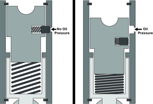
Image source: https://www.vehicleservicepros.com/service-repair/underhood/article/21216014/displacement-on-demand#&gid=1&pid=4
While there are some differences in valve lifter deactivation systems, all systems work largely in the same way. In the case of our example, the Chevrolet V8 engine, GM refers to their version as “lost motion” valve lifters that use pressurised engine oil via a computer-controlled oil control solenoid to decouple the two parts of the valve lifters from each other.
The image above shows how the mechanism works. When pressurised oil acts on the locking pin, the two parts of the valve lifter are decoupled, and the valve lifter is prevented from acting on the affected valve. However, in practice, and apart from disabling the injectors and ignition circuits on deactivated cylinders, cylinders can be deactivated at one of two points in the engine cycle.
In one design, the ECU monitors the position of the pistons in affected cylinders via the camshaft position sensor and deactivates the cylinder by closing the valves when the piston is at the bottom of its power stroke. This traps the exhaust gases in the affected cylinders.
In one other design, the ECU also monitors the positions of the pistons in affected cylinders via the camshaft position sensor and closes the valves after the exhaust stroke, but not before the cylinder had drawn in some air. This traps a charge of air at atmospheric pressure in the affected cylinders.
It is at this point that the give and take process begins. However, to keep things simple and clear, we will discuss each process separately. Let us start with the trapped exhaust gas or air charge that act as-
Air springs
If we assume that a deactivated cylinder is leak-proof in the sense that no air or exhaust gas can escape past the valve seats or through the piston rings, the following happens-
On the compression stroke, the trapped gas or air is compressed, which helps to slow the piston down as it approaches TDC, just as it would have done had the cylinder not been deactivated.
However, on its subsequent downward motion, the cylinder’s volume increases rapidly, but instead of expanding, as a combusting air/fuel mixture would have done, the trapped gas/air is “stretched out” as the vacuum increases, which has the effect of slowing down the piston's motion as it is dragged downward by the rotating crankshaft.
Since deactivated cylinders are always arranged in opposite pairs, the opposing forces created by first compressing the trapped gas/air, and then stretching it out to create a vacuum, cancels out the effects of their reciprocal motion(s). Put differently, this means that the air spring effect largely mimics the effect of torque inputs on the crankshaft, which damps out the excessive torsional vibrations and deformations of the crankshaft that would have been caused had the deactivated cylinders been empty.
In theory, the air spring effect would last for an indefinite number of engine cycles, but since no engine features perfect cylinder sealing, the trapped exhaust gas or air charge will eventually leak past the valves and/or piston rings. Sadly, there is no technical information available on how this issue is addressed on current development models, but one would assume that the misfire detection system would play some role in this.
For instance, since the air spring effect mimics torque inputs to both stabilise the crankshaft and to maintain the engine’s dynamic balance, a reduction in the air spring effect would almost certainly begin to produce measurable cyclical changes in the crankshaft’s rotational speed. Therefore, it is likely that the misfire detection system would alert the ECU to a deteriorating air spring effect, and the ECU will likely disable the displacement on demand system momentarily to “recharge” the deactivated cylinders to restore the air spring effect.
Reduced frictional losses
Frictional losses in cylinders have two causes. The first is the normal sliding friction between the piston rings and the cylinder wall, and the second is the side loads that uneven combustion places on pistons.
In practice, normal sliding friction is not reduced when a cylinder is deactivated. However, when an air/fuel mixture is not ignited, the side loads on pistons in deactivated cylinders do not occur, and as a result, none of the torque output of active cylinders is used to overcome the additional friction load.
Therefore, the active cylinders are more efficient, since they do not have to sacrifice any of their thermal efficiency to overcome the added friction that comes with combustion.
Increased airflow rates increase thermal efficiency
When an engine runs at a steady speed, the manifold vacuum remains constant. However, when 50% of the cylinders are suddenly deactivated and no longer pulls in air, the airflow rate decreases by 50%, and as a result, the manifold vacuum decreases significantly.
Thus, when a displacement on demand system is activated, the ECU increases the throttle opening to improve airflow through the intake manifold. Moreover, the ECU opens the throttle by a bit more than is strictly required, which has the effect of damping out oscillating pressure waves in the intake manifold that result from the opening and closing of the engine valves.
In practice, the improved airflow and smaller (or no) pressure waves mean that the active cylinders actually draw in a bit more air than they would have been able to do if all the cylinders were active. While this is not a form of "forced induction", more air translates into improved combustion, which increases the thermal efficiency of the active cylinders by measurable amounts, which brings us to-
The single biggest driving force behind the development of displacement on demand engines is the need to reduce exhaust emissions from engines with large displacements, and based on currently available test data, these systems are hugely successful.
For instance, during one recent real-world test of a V8 engine with a displacement on demand system, the results showed that the displacement on demand system was active for 17% of the time during an extended test drive in city traffic. This resulted in a 7.7% increase in fuel efficiency.
During highway driving in the same test cycle, the displacement on demand system was active for 48% of the time, which resulted in a 17% increase in fuel efficiency. Moreover, live data collected during this particular test cycle showed that the V8 engine ran on four cylinders for 40% of the total driving time.
Similar tests by other manufacturers showed that fuel savings of between 6% and 25% are possible, depending on the engine and the driving conditions, with highway driving at steady cruising speeds producing the highest fuel savings, which begs this question-
Some could probably be, but the specific vibration and acoustical characteristics of many engines could make it impossible simply to retrofit these engines.
For instance, the flow dynamics of the intake and exhaust systems might be matched when all the cylinders are active, but deactivating 50% of the cylinders could disrupt the airflow through the intake system on some engines to the point where the active cylinders might be starved of air. Similarly, reducing the exhaust stream by 50% could have serious negative consequences for exhaust scavenging. In practice, the reduced exhaust flow could actually block or restrict the exhaust system, because of the increased distance between the high-pressure “slugs” of exhaust gas.
As a result, displacement on demand engines have intake and exhaust systems that are specifically tuned to meet the specific air/gas flow demands that come with using only 50% of the engine’s cylinders.
Moreover, deactivating 50% of the cylinders on an engine change the points (in degrees of rotation) where torque inputs are applied to the crankshaft. For instance, if four of the eight cylinders on a V8 engine are deactivated, the distance between torque inputs increase from 90 degrees to 180 degrees.
NOTE: On V6 and V10 engines, a displacement on demand system will only deactivate two, and four cylinders, respectively, as opposed to deactivating 50% of the cylinders as is the case with V8 and V12 engines.
In both examples, the frequency of harmonic vibrations has increased by 50%, while the natural damping effect of opposing reciprocal forces have decreased, despite the pronounced air spring effect that deactivated cylinders produce.
Thus, as a practical matter, new displacement on demand engines designs have firing orders that place two deactivated cylinders next to each other on each bank of cylinders. In practice, this creates a system where only the front or rear half of the engine works, while the inactive half serves to damp out dynamic imbalances.
However, the engine’s dynamic balance is only preserved for as long as the air spring effect in the deactivated cylinders can match the force of the torque inputs made by the active cylinders, which leaves us with this-
There is no doubt that each manufacturer will eventually come up with their own names and acronyms for displacement on demand designs. However, the laws of physics dictate that there will be a strictly limited number of ways that these systems can be implemented, which is good news for us, as technicians.
Regardless of what any manufacturer calls its displacement on demand system, the upside for us is that all systems will largely work in the same way, and fail for much the same reasons. Therefore, if we understand the basic principles of these systems, diagnosing and fixing them should not present any of us with undue difficulties.
