During a recent consultation regarding a non-starting Audi Q7, this writer was privy to a conversation between two technicians who were discussing the possible reasons why a particular 20-amp fuse on a late model Toyota Prius would blow as soon as they inserted it into the fuse box. Since the two vehicles were in adjacent bays, it was easy for this writer to hear the two technicians discussing voltages, currents, short circuits, and abnormal resistances, until one technician suggested referring the vehicle to the dealership. The other technician agreed with this recommendation, adding that "The electrics on hybrids are so weird that anything is possible, so I just wish they would make the electrics on hybrids the same as on proper cars."
At the time, it was not this writer’s place to comment or offer assistance, but in this article, we will demonstrate that hybrids do not have “weird electrics”, and that the high-voltage electrical circuits and systems on hybrid vehicles follow the same laws and principles that the electrical circuits and systems on "proper cars" do. The only differences between hybrids and "proper cars" are that in a few cases, some laws or principles of high-voltage electricity are applied in ways that do not (always) have direct analogues to the low-voltage systems and circuits on conventional vehicles.
Before we get to specifics though, and if you are not an auto electrician, it might be worthwhile to revisit some basic electrical theory, if only to demonstrate that all electrical circuits and systems are subject to the same laws. Let us start with defining some of the most commonly used terms in automotive diagnostics-
Voltage is defined as the amount of potential energy between any two points in an electrical circuit. In engineering terms, however, voltage is the potential difference in energy between any two points (in a circuit) that will impart one joule of energy/Coulomb* of charge to any part of the circuit through which the voltage flows. Fortunately, car manufacturers have done all the calculations for us, and we only have to look up specified voltages in published service information. In wiring diagrams and schematics, voltage is represented by the letter “V”. Somewhat confusingly though, in equations and formulae, voltage is typically represented by the letter “E”, as short for “Electromotor force”.
*Coulomb’s Law describes (among other things) the operation of electric motors and generators, but since limited space precludes a comprehensive discussion of Coulomb's Law, we will discuss it in some depth in a follow-up article.
The best way to visualise current is to think of a hose through which water is flowing: the higher the pressure behind the water becomes, the more water flows through the hose. Thus, if we wanted to know how much water is flowing through the hose, we would measure the flow of water through the hose over a fixed amount of time.
Electrical current, measured in “Amps”, works in the same way, but instead of volume, we measure the number of Coulombs, typically measured per second, that pass through any point in a circuit. Note that in engineering terms, one Coulomb is equal to one Amp, which is in its turn, equal to 6.241 × 10¹⁸ electrons passing through any point in a circuit per second. In wiring diagrams and schematics, current is represented by the symbol “I”.
Electrical resistance is analogous to a restriction in a hose that prevents the free flow of water through the hose. In electrical circuits, however, restrictions are typically corroded or poor connections that prevent the free flow of electrons through conductors across the corroded or poor connection. In practice, and from a diagnostic perspective, the higher a resistance becomes, the less current will flow across the "restriction" but note that this relationship is not linear since abnormally high resistances can be overcome by increasing the current, albeit only up to a point.
In engineering terms, resistance is measured in “Ohm”, with one Ohm being the difference between two points in a circuit where one volt will “push” one Amp across the difference. In wiring diagrams and schematics, resistance is represented by the Greek letter “?”.
Let us now consider-
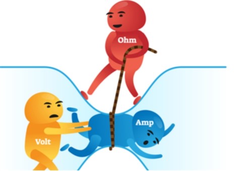
The above terms and their definitions apply to all electrical circuits, regardless of any given circuits’ strength, intensity, or purpose. However, from our perspective as technicians (and not necessarily auto electricians) the terms and definitions listed above have very little, to no meaning if we consider them individually. The best way to understand the role of each of the above terms when we are looking for a fault in an electrical system is to consider them together as a three-legged stool that can only remain stable if the three legs are of an equal length.
In practice, all electrical circuits, regardless of whether a circuit controls the wipers on a conventional vehicle or the high-voltage battery's rate of charge on a hybrid vehicle, are designed to have all three "legs" of the stool present. We can extend our stool analogy to the seat of the stool, in the sense that the seat represents the purpose of a given circuit. Thus, in practice, an electrical circuit will have voltage, current, and built-in resistances that are calculated so that the circuit can perform its intended purpose, i.e., hold the tool’s seat up, or more precisely, make the wipers work, manage the charging of a high-voltage battery, or do whatever else the circuit is designed to do.
The purpose of a circuit will dictate the “length” of the legs in terms of voltage, current intensity, and total resistance, but no electrical circuit can work as designed if a) one of the “legs” is missing, or b), if the relationship between the “legs” becomes so unbalanced that the stool topples over. One example of an unbalanced circuit would be when the wipers on a vehicle stop working because corrosion across a connection in the circuit had become so severe that the fixed 12 volts that drive the system cannot push enough Amps across the poor connection to energise the wiper motor.
Fortunately, we do not have to calculate the length of our hypothetical stool's legs every time we look for the cause of an electrical fault. We can simply look up the voltage, current, and resistance values in service information, but again, none of the values means anything in isolation. We need to consider each of these values relative to the "lengths" of the other legs and to do that more easily, we can always refer to-
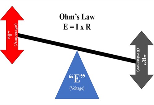
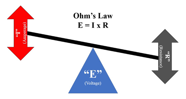
Image source: https://www.searchautoparts.com/sites/www.searchautoparts.com/files/images/ma0118-e1.png
From a diagnostic perspective, Ohm’s law is arguably the most effective tool we have at our disposal to diagnose issues in any electrical circuit, regardless of the circuit’s purpose. Consider the graphic above-
Ohm's Law is expressed in writing as “E = I x R”, where-
Thus, if we consider the graphic, we see that it represents the relationships between voltage, current, and resistance. This graphic also shows how two values MUST change if one other value changes. For instance, if the voltage is fixed, and resistance increases, amperage (current) MUST decrease since not all of the available current can pass across a poor or corroded connection. This condition typically results in symptoms such as dim lights, slow wipers, and slow radiator cooling fans and the like, because the intensity of the current is insufficient to drive these systems.
Similarly, if the voltage is fixed and the resistance decreases, the amperage (current) MUST increase because one or more failed or missing resistances can no longer regulate the current's intensity. This condition typically results in blown fuses, because say a say, 15-amp fuse is not designed to cope with say, 25 Amps that result from the loss of some resistance in the circuit. Incidentally, this is why we rarely see say, over speeding radiator fans or wipers: while increased currents might cause over speeding, the fuses that protect these circuits typically blow before we see the effects of excessive currents in circuits.
NOTE: While fuses in high-voltage circuits blow for the same reasons as fuses in low-voltage circuits, high-voltage fuses do not blow as easily. These fuses are so-called “slow-blow” fuses that take considerably longer to blow than normal fuses to give control modules a) time to attempt to correct some types of problems that occur in high-voltage circuits, and b), to protect control modules from immediate damage caused by excessive currents and/or resistances
Thus, as a practical matter, electrical diagnostics revolves around investigating the relationships between voltages, currents, and resistances in circuits, but to understand how these relationships are applied in practice, we need to look at the two principal types of circuits used in vehicles. Let us start with-
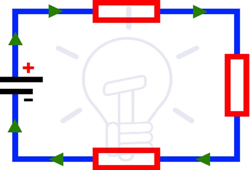
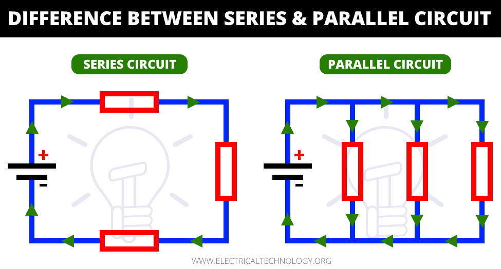
Image source: https://www.electricaltechnology.org/wp-content/uploads/2020/05/Difference-Between-Series-and-Parallel-Circuit.png
This graphic represents a series circuit, in which a current can only flow along one path. As shown here, current leaves the power source through one terminal, and flows along the circuit path through one or more loads (aka consumers), before returning to the power sources' opposing terminal.
In practical terms, series circuits are analogous to a road that has no passing lanes, thus forcing vehicles to follow one another in one direction only. Therefore, if something like a pothole or a broken-down vehicle slows the lead vehicle all the other vehicles on the road have to slow down as well. In electrical circuits (like a starter motor circuit), an obstruction could be something like a frayed starter cable that inhibits the free flow of current through the frayed part.
In the above example, the "blockage" caused by the frayed part of the cable increases resistance, thereby reducing current flow, which explains why the starter motor does not work as well as it should. As a practical matter, the highest current that can flow through a series circuit is limited to the amount of current that can flow through the "weakest" part of the circuit. In this example, the weakest point in the circuit is the frayed part of the starter cable.
Some other examples of series circuits include both high-voltage hybrid battery packs, and the six cells in a normal 12-volt battery. In both cases, battery cells are connected in series (positive to negative) in a pattern that adds the nominal voltage of each cell to the nominal voltage of the next cell in the series. Note that all batteries follow the most important rule of series circuits, in the sense that a battery's output is limited to the maximum output of the battery's weakest cell.
Thus, in a low-voltage system, a weak battery cell could result in a no crank situation because current to the started motor is limited by an excessive resistance, while on a high-voltage hybrid vehicle, an excessive resistance could cause reduced current reaching the electric motor, thereby reducing vehicle performance. On hybrids, this aspect of high-voltage battery operation is managed by a dedicated control module that monitors the battery continuously to detect weak or damaged cells, which brings us to-
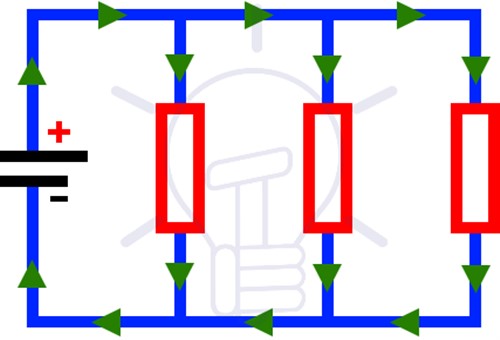
Image source: https://www.electricaltechnology.org/wp-content/uploads/2020/05/Difference-Between-Series-and-Parallel-Circuit.png
This graphic represents a parallel circuit, which is a circuit in which current can flow from, and back to, the power source along multiple paths. This type of circuit is typically used in exterior lighting systems, and particularly on head-, and taillights, because if one circuit path fails and one headlight goes out as a result, current can follow a different path to reach the other headlight.
In practice, a parallel circuit is one in which all the components in the circuit are connected across contacts that are common to all the components in the circuit. One practical example of this is the way headlights are wired. Since both headlights are connected to the battery, each headlight receives 12 volts from the battery. However, if each headlight has a resistance of say, 10 Amps, the total current drawn from the battery would be 20 Amps, since the combined currents in a parallel circuit are always equal to the sum of the currents in each possible pathway in the circuit. Note that this example excludes the resistance values of the taillights, which are typically included in headlights’ parallel circuits.
Unlike series circuits, though, parallel circuits have a secondary application, which is to increase available current without increasing voltage. The most common example of this is the way two 12-volt batteries are connected in some light-duty diesel starting systems. In these cases, the batteries are connected positive to positive and negative to negative; this arrangement doubles the available current (amperage) of each battery, but the overall voltage of the system remains at 12 volts.
While parallel battery connections are rare on traditional hybrid vehicles, it is common on pure electric and plug-in hybrid electric vehicles to increase effective ranges through increased battery capacity. One good example of this is Tesla cars that use hybrid circuits: series battery connections to increase battery voltage, and parallel battery connections (between series battery circuits) to increase available current to boost the vehicle's effective range, which brings us to-
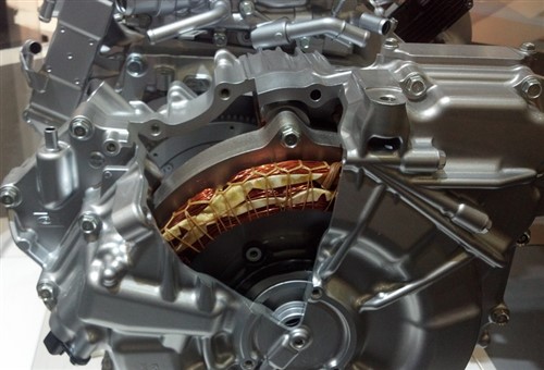
Image source: https://www.searchautoparts.com/sites/www.searchautoparts.com/files/images/ma0118-e5.png
The relationship between magnetism and electricity is not easy to explain in non-technical language, but suffice to say that electricity and magnetism are indivisible because it is not possible to have one without the other. This is true for both high and low voltage circuits, and it is this aspect of electricity that explains why and how the same laws that apply to low voltage circuits, also apply to high voltage circuits.
However, while the same laws apply, magnetic induction can have different applications or purposes. For instance, it can produce ignition sparks on conventional engines, activate shift solenoids on automatic transmissions, or it can drive electric motors on hybrid vehicles. Let us look at this topic in some detail-
In the case of an ignition coil, the primary windings are “charged up” by a low voltage, which creates a magnetic field in the primary windings. When the coil driver shuts this voltage off, the magnetic field collapses: this induces a voltage "spike" in the coil's secondary windings, which spike then becomes the voltage source that supplies the ignition spark.
The same principle applies to create the pulses that drive the electric motor on a hybrid vehicle, but with some "tweaks" added to reduce the power drain on the high-voltage battery. The alternative to these tweaks is to increase the battery's voltage, but that comes at the cost of added weight and higher costs.
Therefore, to save on weight, hybrid systems use so-called "boost" inverters that are connected in series between the high-voltage battery and the DC bus circuit. In practice, this inverter is a reaction coil that is fed with an increased current to create a powerful magnetic field around the coil. However, the biggest difference between the application of magnetic induction in an ignition coil and a boost inverter is that unlike in an ignition coil, the current in the boost converter is not completely shut off. Nonetheless, the partial removal of current still produces significant voltage spikes, which then boost the power that reaches the motor through other circuit paths.
The downsides to this strategy are, however, that a) the switching of the additional current has to be controlled precisely with a dedicated control module, and b), that if a damaged or partially discharged high-voltage battery cannot supply the additional current, the vehicle will exhibit a marked reduction in overall performance, and particularly during acceleration, which leaves us with this-
While this article has barely scratched the surface of electrical theory, we nevertheless hope that it has given you some new insights into the universal applicability of at least some of the laws and principles of automotive electricity, and especially so if you are not an auto electrician.
We also hope that we have demonstrated that hybrid vehicles do not have “weird electrics”. However, while using the same diagnostic principles and strategies that allow diagnostics on low voltage systems also work on high-voltage systems, the complexity of hybrid systems should not be underestimated.
Moreover, electrical diagnostics on hybrids requires special training and equipment, as well as the observance of safety precautions that do not necessarily apply to low voltage systems, so take extreme care when you are working around high-voltage systems.
