Assuming that you are not an expert auto-electrician, what do you do when you encounter a vehicle with an illuminated charging system warning light, and you find one or more stored trouble codes that relate to some aspect of the charging system? More to the point though, what do you do when you encounter a vehicle with severe driveability problems and an illuminated charging system warning light, and you find trouble codes that relate not only to the charging system but to a slew of seemingly unrelated systems as well? Do you routinely refer such vehicles to the electrician in your workshop?
In some cases, referring a vehicle would be the prudent thing to do because some charging system issues can be extremely challenging to diagnose and repair. However, many charging system issues are not only common to (almost) all vehicle brands and models; they are also relatively easy to diagnose and repair. In fact, in the majority of these cases, all you need to perform accurate diagnoses and definitive repairs is a working knowledge of how charging systems work, as well as some basic tools and test equipment. In this article, then, we will discuss some basic charging system operating principles and share some diagnostic tips and tricks. Let us start with this cautionary note-
Although modern charging systems have hardly changed in terms of their general operation, layout, and componentry, it would be a mistake to underestimate the complexities of the technical implementation of how these systems keep modern electrical systems powered up.
We need not delve into the minutia of how modern charging systems work as compared to how they did forty years ago, but it is nevertheless important to understand that the dozens of control modules in modern vehicles require levels of current and voltage control that are impossible to achieve without the extensive use of microprocessors. Also, it must be noted that to meet current exhaust emission control regulations, car manufacturers have had to increase the efficiency of modern charging systems to reduce fuel consumption, and by extension, exhaust emissions.
In terms of practicalities, the requirement to both improve current/voltage control and reduce exhaust emissions have led to the development of alternators that-
As a practical matter, these increases in efficiency result from three principal advances, these being-
Taken together, the advances outlined above have greatly increased the overall efficiency of modern charging systems, but there are downsides, as well, these being the facts that-
Nonetheless, modern charging systems are still prone to much the same issues, failures, and malfunctions as before and many test procedures remain largely the same, although in some cases, some of the test parameters we have used in the past, such as the ubiquitous 14.2V charging voltage, no longer apply in many cases. Let us look at one such parameter, but note that-

Note that while battery capacity remains as important as ever, the type of battery that is installed in a vehicle is an even more important factor. For instance, AGM (Absorbent Glass Mat) and ECM (Enhanced Cyclic Mat) batteries, both of which are used in stop-start vehicles, have chemistries that differ greatly from the relatively simple chemistry of “normal” flooded lead-acid batteries.
We need not delve into the finer details of battery chemistries here, beyond saying that both AGM and ECM batteries have to keep multiple electrical systems working when the engine in a stop-start vehicle is not running. Moreover, since AGM and ECM batteries must also supply starting power several thousand times more often than a lead-acid battery, a lead-acid battery cannot meet the demands of vehicles with stop-start technology.
Note though that while ECM batteries, aka Advanced Flooded Batteries or Enhanced Flooded Batteries, are in essence nothing more than advanced lead-acid batteries, both AGM and ECM batteries have deep-cycling properties and enhanced capacities that normal lead-acid batteries do not have. As a result, both AGM and ECM batteries have charging profiles that differ from those of normal lead-acid batteries.
For instance, AGM batteries are not only extremely sensitive to even marginal overcharging but these batteries also typically require charging voltages of between 14.6V and 14.8V after a deep discharge, while standby charging voltages range from 13.6V to 13.8V up to a battery or ambient temperature of 50 degrees Celsius. Note also that these charging voltages represent a maximum of 20% of the battery’s capacity; if a charging voltage exceeds this maximum limit, the battery is overcharging, and fatal damage to the battery is assured.
The above is just one example of why it is critically important to verify that the correct battery is fitted to the vehicle every time you diagnose a charging system issue. In practice, modern charging systems are not only built around battery types, but most modern charging systems also use advanced algorithms and other control and monitoring strategies to maximise both battery performance and battery life, which means that if the wrong battery is fitted to a vehicle, neither the charging system nor the battery monitoring system can perform as intended.
Therefore, before you draw conclusions or make inferences about the condition of the charging system as a whole, we recommend that you first verify that the correct battery is fitted to the vehicle and that a battery reset procedure was performed after the last battery replacement.
Having said the above, let us look at what is arguably the most common issue that afflicts modern charging systems (after wrong, unsuitable, or defective batteries), this issue being-
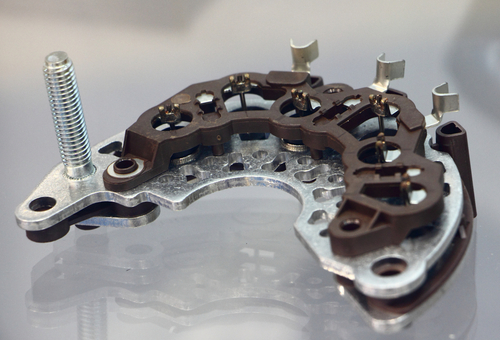
The image above shows a typical bridge rectifier, one of which is an integral part of all alternators. In practice though, the words “rectifier” is a bit of a misnomer since the AC an alternator generates is not so much rectified, as it is converted into DC, which is the form of electricity that all electrical consumers on vehicles use because direct current is more efficient than alternating current in automotive applications.
We need not delve into the complexities of electrical theory here, beyond saying that the term "bridge rectifier" derives from the fact that one end of each of the three stator windings is connected to a "bridge" wire that connects one positive and one negative diode in series. Since the alternator stator has three windings, the rectifier unit has three sets of diodes, and each set of diodes acts as a kind of one-way check valve that allows alternating current to pass through the diodes in only one direction, which has the effect of "smoothing" out the current flow from the three phases of the alternator's windings.
Thus, if, a), there are no short circuits in the alternators’ windings, and b), all the diodes in the rectifier are working properly, it follows that each phase of the alternator's output will follow the preceding phase in a predictable pattern as the rotor rotates. In practice, the three phases of an alternator's output are separated by 120 degrees, and, therefore, a waveform of an alternator's output will consist of a series of equally-spaced wave peaks that all have the same amplitude. Consider an example of just such a waveform below-
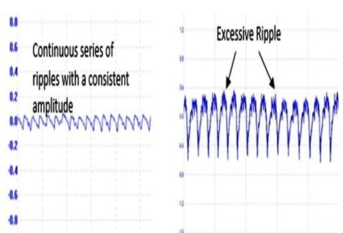
Image source: https://resources.pcb.cadence.com/blog/2020-bad-alternator-diodes-automotive-systems-and-electronic-design
Note that while wave peaks in the waveform on the left all have roughly the same amplitude, the slight differences between wave-peaks amplitudes do not repeat in a fixed pattern, which is indicative of an alternator that is working perfectly. Moreover, since only the wave peaks in this type of waveform have any diagnostic value, you can safely disregard the troughs or tails in the waveform.
The waveform on the right, on the other hand, shows wave peaks that differ in amplitude in an almost sinusoidal pattern, which is indicative of one pair of diodes that is allowing excessive amounts of alternating current to pass into the electrical system. This is known as excessive “AC ripple current”, and its effects can be unpredictable, if not always fatal to electrical components and/or control modules.
Nonetheless, depending on the vehicle and degree of excessive AC ripple current, typical symptoms could include some or all of the following-
Note though that not all of the above symptoms will necessarily be present in all cases of excessive AC ripple current, but if you encounter strange combinations of symptoms that don’t make sense, you can save a lot of diagnostic time by-
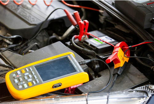
The simplest and still one of the most effective tests for bad diodes in alternators is to set a multimeter to the 12V range on the AC scale, and then to take a reading across the battery terminals while the engine is running. Any AC voltage, no matter how small, indicates one or more bad diodes, and while the alternator can be repaired in most cases by replacing the rectifier, we recommend that you confirm the AC reading by obtaining a waveform of the alternator's output before you remove the alternator from the vehicle
This test is also very simple: connect one port of an oscilloscope to the alternator's output cable, and ground the circuit to battery negative. Set the scope to record at least five seconds worth of data with the engine running, but make sure you set the wave amplitude high enough to make any differences in amplitude clearly and easily visible. Note though that you will likely never get exactly equal amplitudes, but what you are looking for are amplitudes that vary in a discernible pattern. Small differences that occur in an irregular or random way are typically the result of electrical noise, and can therefore be disregarded, but what cannot be disregarded is something one might not necessarily associate with charging system issues, this being-
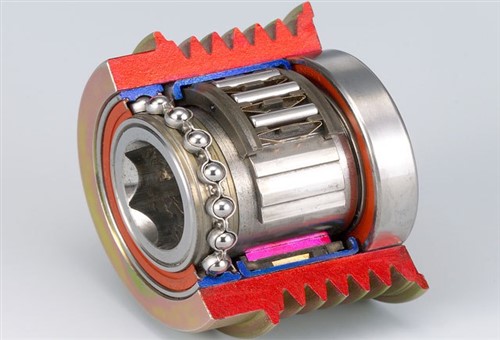
Image source: https://www.nsk.com/products/automotive/power/electrical/images/4102_P031_4.jpg
We mentioned exhaust emission regulations earlier, and one of the ways manufacturers are meeting current regulations is to a) use one-way pulleys like the example shown here on alternators, and b), to reduce the tension of the serpentine drive belt to reduce parasitic power drains caused by an overly tightened belt.
One way to reduce the belt tension is to reduce the spring tension in automatic tensioning devices, but how well this works depends on both the routing of the belt, and the number of pulleys the belt must pass over. In practice though, it turns out that while high-efficiency alternators can be driven successfully with lower tensions on drive belts, sudden changes in engine speed can produce momentary belt squeal.
For instance, if the engine speed rises suddenly, the belt can squeal as it slips on the alternator pulley because of the pulley’s small bend-radius. However, while this is more of a nuisance than anything else, suddenly decreasing the engine speed can throw the drive belt off one or more pulleys if a low-tension tensioner fails to maintain proper tension on the drive belt's return side.
To overcome this, car manufacturers have started to introduce alternator pulleys that incorporate a type of clutch that disengages automatically when the engine speed decreases suddenly. Considering that an alternator rotor can spin at anything between 8 000RPM and 10 000RPM at high engine speeds, a sudden reduction of the engine speed means that the momentum of the rotor forces the pulley to rotate against the friction of the drive belt.
Thus, by disengaging the clutch in the pulley, the alternator rotor can rotate independently of the pulley until its speed again matches that of the pulley, at which point the clutch engages automatically, and the drive belt once again begins to drive the alternator via the pulley. It is important to note that since the clutch in the alternator pulley allows the tensioner to maintain an even tension on the belt’s return side at all times belt squeal is eliminated, and belt life is extended, at the same time.
However, one-way pulleys, such as the example shown above, contain lots of moving parts that depend on proper lubrication to work as designed. In fact, one-way pulley failures as the result of lubrication failures and excessive mechanical wear are among the leading causes of catastrophic charging system failures. While some pulleys merely disintegrate when they fail, other failure modes can cause the alternator shaft to shear off, which typically happens when the pulley fails to disengage at high rotational speeds.
Given the above, it should be clear that one-way alternator pulleys have finite service lives. Therefore, to prevent pulley failures and the accompanying damage that results from a drive belt flailing around the engine bay at ballistic speeds, it is critically important that you verify the condition of one-way alternator pulleys during a) every scheduled service, or b), every time you do any work on the charging system.
It only takes a minute; remove the drive belt and verify that the pulley rotates freely in its reverse direction. There should be no noises, no evidence of leaking lubricant, no catching, binding, or excessive resistance to movement, and particularly no sideways free play. When in doubt, the safest course of action is to replace both the pulley and the drive belt, but note that drive belts intended for use with one-way pulleys are typically directional. This means that the belt's intended direction of movement is typically indicated by an arrow or a similar indicator printed on the belt, and getting this wrong can cause continuous belt squeal and premature belt failure, which leaves us with this-
If there as one guiding principle that ruled charging system diagnostics, it would be this- “Close enough is not good enough”, and this applies to all aspects and components of the system.
Modern systems do not allow for large deviations from specified operational parameters. Batteries must be charged to capacity before testing, and all batteries must be of the correct type, capacity, and rating. The alternator's output must be free of AC ripple currents, and the alternator's output must not be improperly limited by either the power management control module or the voltage regulator if the alternator has a separate regulator. All connections must be clean, tight, and free of corrosion, and only specified cabling must be used for high-amperage circuits if you have to perform wiring repairs.
While all of this might sound like a tall order if you are not an expert auto-electrician, most, if not all of this information is available online, and in most cases, it is available on resources that do not require expensive subscriptions. In today's competitive environment, getting all of the basics right is half of the battle won, and much of the rest is won by performing some simple tests with the equipment you already own. So, are you ready to tackle at least some charging system issues?
