There is no denying the fact that you learned many things in trade school, and if you are a newly qualified mechanic, you probably remember most of it. However, there are also many things trade schools don’t teach, such as for instance, how to apply the electrical theory they taught you to practical electrical diagnostics in a busy workshop. This writer has often observed the huge disconnect between trade school theory and workshop practice first hand, and while it is possible to bridge this gap, doing so successfully often requires that newly qualified mechanics unlearn or reassess much of what they had learned in trade school. Thus, in this article, we will explore this process by greatly simplifying diagnostic approaches to three commonly occurring electrical problems. Let us start with-
Electricity has always been a part of what made cars run and up to 1955, all cars used 6-volt electrical systems to power lights, ignition, and starting systems. While the introduction of 12-volt systems in 1955 allowed the use of accessories like rudimentary air conditioning systems, simple power windows and variable-speed interior ventilation fans, the fabric-covered wires of the time were extremely prone to short-circuiting because the insulation absorbed moisture like sponges.
This tendency was largely eliminated by grounding electrical systems on the positive side, which had the added advantage that is also greatly reduced the incidence of galvanic corrosion in engine cooling systems. Although PVC-coated electrical wire became available during WWII, the new and highly improved wiring was only adopted by car manufacturers during the late 1950s, which meant that until comparatively recently, finding and fixing major short circuits caused by wet wiring was the defining feature of electrical diagnostics on all types of vehicles.
Nonetheless, the development and use of waterproof wiring greatly improved the integrity of automotive electrical systems, and while the new wiring made it possible to ground electrical systems on the negative side, this also reintroduced galvanic corrosion processes into engine cooling systems but that is a topic for another time, so let us move on to-
We are not suggesting that what you had learned in trade school is wrong or inappropriate, but very often trade schools overemphasise the teaching of electrical theory and circuit design at the expense of teaching common-sense diagnostic principles.
It’s not a bad thing to know everything about electrical theory but under real-world conditions, such as those that obtain in busy workshops where nobody has the time to teach you basic diagnostic skills, much of what you know about electrical theory becomes somewhat irrelevant. Under these conditions, it becomes much more important to know that the progression of electrical faults generally follow patterns than it is to be able to recite Ohm’s Law in your sleep, which is not necessarily a skill employers are interested in when they are looking to fill job vacancies.
It is however not for this writer to say how you should impress prospective employers or your current employer for that matter, but it does help to think of the principal characteristics of electricity like resistance, amperage, current, and voltage as pillars that support the correct operation of all the electrical systems in cars. When you view electricity in this way, it becomes easy to reduce electrical problems and their diagnoses to either a), one of the pillars of electricity being absent, or, b), an imbalance in the relationships between resistance, amperage, current, and voltage.
Nonetheless, it must also be stated that the importance of each pillar and its relationships to other pillars is vastly greater now that it has ever been. This is simply because almost all control modules on modern vehicles are a), extremely fault-intolerant, and b), there are vast numbers of wires and circuits on modern vehicles for faults to be present in, which brings us to the topic of-
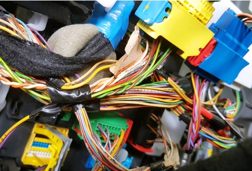
Despite the great complexity of modern automotive systems, these systems still depend on the main pillars of electricity i.e., resistance, amperage, current, voltage, and continuityto work as designed. However, it has been this writer’s experience that many new mechanics take one look at a wiring harness or crow’s nest of wires under a fuse box or dashboard and then go into panic mode simply because they can't see a tree for the forest, in a manner of speaking. In terms of electrical diagnostics, the fault is the tree, while the forest is the multitude of wires, fuses, relays, sensors, control modules, switches, and other consumers that link all the wires together.
There is no shame in going into panic mode when you are new to the car repair trade, but this writer would like to suggest that when you do go into panic mode, you get out of it by looking at an automotive electrical system in another way. What is important to remember is that while electrical consumers do link wiring together, it is more accurate in a technical sense to say that it is wiring that links all electrical consumers to a power source on one side, and a ground connection on the other.
Once you make this distinction, it becomes easier to, a), see individual trees in a dense forest, and b), to discern specific and individual paths to each tree through the forest. Put in another way, this means that instead of seeing a mass of wiring, you begin to see individual circuits that link specific electrical consumers to a power source on one side, and a ground connection on the other. As a practical matter, the ability to see or visualize individual circuits within the greater electrical system allows you to design diagnostic procedures that home in either on the “Before”, or “After” part of an electrical circuit. Let us use a simple practical example of this principle by considering the image below-

This image shows a battery powering a light bulb, and we all know that for the bulb to shine the circuit needs to be complete. However, what happens if we remove the positive connection from the battery? Of course, the bulb stops working and while we are certain that you are fully conversant with the scientific principles behind the bulb's failure to shine, we are not discussing electrical theory at work on a test bench. What we are discussing is how to figure out why an electrical consumer on a high-end vehicle has stopped working, so let us return to our "Before" and "After" analogy.
In this case, the “Before” includes everything between the power source and the light bulb. This typically includes the power source itself, all relevant control switches, wiring, fuses, relays, and other components that make up the system up to the point where work is performed. On the "After" side, we include everything between the light bulb, or the point where work is performed, and the ground connection. Something is missing, however, and that is the "Between", which in this case, is the light bulb that represents our non-functional electrical consumer.
Thus, since this analogy forms the basis around which (almost) all electrical diagnostic procedures can be built, let us see how the light bulb analogy can be applied to modern automotive electrical diagnostics, starting with-
Also known as, “incomplete circuits”, these circuits are exactly what their name implies; circuits that are not complete. There are many possible reasons why a circuit cannot be completed, but for the most part, these causes include blown fuses/fusible links, broken/disconnected wiring, and mechanical failures of control switches, among many others.
Regardless of the cause though, it never helps to take the view that “The fault can be anywhere in the circuit”. What does help is to apply the light bulb analogy to the problem, and here is how-
Say we remove the negative connection from the battery: the light goes out, but there is still current in the wire between the power source (battery) and the bulb, which is where work would be done if the negative connection were not removed. In fact, the positive wire is an extension of the positive battery terminal, but since the connection between the bulb and the ground connection (negative terminal) is removed, the current cannot return to the negative battery terminal, and the circuit is said to be open or incomplete.
This is easy to demonstrate on a test bench, but matters are somewhat more complicated on an actual vehicle since current will flow through a circuit for as far as it can between the power source and the consumer before it is interrupted. Therefore, the first thing to do is to locate the non-functional consumer and to start checking its power feed from the power source to the first point along the circuit where it could conceivably be interrupted. This could be a control switch, relay, fuse, or other control mechanisms, all of which will be indicated on a wiring diagram.
If the specified current is present beyond the first possible point of interruption, continue checking along the circuit until you can verify that the specified current reaches the consumer: if it does, you need to check if the consumer actually works. If it does work, you know that the fault is present between the consumer and the ground connection, in the ground connection itself, or in the (grounded) consumer.
While the above might seem obvious and self-evident to experienced technicians, the advantage of this approach to newly qualified mechanics is that nine times out of every ten, the fault might be found and fixed in far less time than it would have taken an inexperienced mechanic to open an entire, complex harness in the hope of stumbling upon the cause of the problem.
Poking around in complex wiring harnesses with back probes or other test equipment is never a good idea, so always avoid potentially expensive mistakes by reducing the problem you are dealing with to its simplest form, such as our light bulb and battery example, which brings us to-
These circuits are also exactly what their name suggests; circuits that follow a shorter path to earth or ground than they are supposed to. In modern automotive electrical systems, circuits are usually protected against overloads by fuses between the power source and an electrical consumer, so if we apply our light bulb and battery analogy to automotive diagnostics, our example circuit would be protected by a fuse between the battery and the positive connection on the bulb.
The above might also seem self-evident, but with short circuits, you need to ask yourself this question- "Where in the circuit is work being done?" In our example circuit, the work takes place at the light bulb (the bulb lights up), so for the circuit to be shorted, there has to be a path to ground that starts somewhere between the fuse and the bulb.
The same thing happens on a vehicle. For instance, if an anomalous path to ground started after the consumer, the fuse would not blow because the supply current would simply flow through the consumer, thus causing it to work. If however, the anomalous path to ground started between the fuse and the consumer, or within a grounded consumer itself, the supply current would by-pass the consumer and run straight to ground through the fuse. If the consumer’s normal current draw were, say, 25 Amps, the power source would now send its full amperage to ground through the anomalous path, and since a 25-amp fuse cannot cope with a modern battery's 100 or so Amps, the affected fuse will blow as a result.
As with open circuits, it always helps to reduce short circuits to their simplest form. In this case, it is the fact that fuses can (generally) only blow when an anomalous path to ground is established between the fuse and the work/consumer or within the grounded consumer: never after the consumer because that would only establish an additional grounding point, which brings us to our last common electrical issue, which is-
The term "voltage drop" is simply a generic term for issues that older technicians knew as "bad connections", “loose connections", "low voltage", and others that referred to conditions in which less than a specified current reached an electrical consumer. As a practical matter though, voltage drops can occur on the positive side of a circuit as easily as it can on the negative side, but one common characteristic of reduced voltage issues is the very high likelihood that the cause of the issue will generate high temperatures both in wire terminations and in the wiring itself.
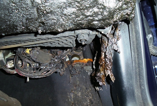
The image above is an example of what could happen when a wire termination on a high-amperage circuit becomes damaged or works itself loose. Of course, voltage drops do not always set cars on fire, but on some circuits, such as for instance, reference voltage circuits, a drop of just one volt as the result of a poor connection can have dramatic negative effects on several engine management systems and/or functions because several systems share one of two reference voltage circuits.
As with other electrical issues, the easiest way to find bad/poor/loose connections is to reduce the problem to its simplest form. In this case, the problems’ simplest form is the fact that less than perfect connections generate heat as resistance rises across the bad connection, which means that the diagnostic process should start by looking for anomalous sources of heat in wiring harnesses, junction boxes, fuse boxes, and connectors with a thermal imager.
The alternative is opening harnesses and randomly disconnecting connectors, but doing this is not only counterproductive because it wastes time, but it is also looking for trouble because you could disable one or more control modules in the process of randomly disconnecting connectors.
Note though that it is important to compare proverbial oranges with oranges when you are chasing down voltage drop issues. For instance, return-less fuel systems use control module induced voltage reductions to control fuel pressure by varying the fuel pumps’ speed, so having a Eureka! moment when you discover a voltage drop in such a fuel system (or other pulse width modulated circuits) is often a case of comparing oranges with apples, which leaves us with this-
The intention of this article is not to have newly qualified mechanics underestimate the complexity of modern automotive electrical systems, which would be a mistake. The primary purpose of this article is to inspire new mechanics to recognise that since these systems are so complex, it is always possible to reduce any complex problem to manageable, “bite-size” pieces, and then to use their greatest asset, which is their ability to think critically, to analyse each component of the problem in a logical manner to arrive at a definitive diagnosis.
