As technicians, most of us have clearly defined comfort zones that many of us will only move out of under exceptional circumstances. Most of us will also agree that there are very good reasons why so many of us choose to specialize in one particular area of automotive diagnostics and/or repair, not the least of which is the fact that modern vehicles have become so complex that, nowadays, it is impossible to know everything about everything or even everything about most things.
Sometimes, though, we are forced by circumstances to tackle diagnostic issues in areas that fall outside of our comfort zones, as recently happened to a young technician that found himself alone in his place of employment, which was a small three-bay establishment. The customer turned out to be a recent immigrant who chose to bring his car with him, and whose engine was on the verge of overheating. While overheating engines was nothing new to this young technician, the problem, in this case, was that he had never seen this engine before and therefore, he had no idea where to begin to diagnose the problem.
Thus, being in a bit of a bind, the young technician called his employer for guidance, who authorized him to call in a consultant, who in his case, turned out to be this writer. We can skip over the details of why the young technician, who incidentally, specialized in mechanical repairs, was alone in the workshop but at this point, we must mention the fact that the import vehicle is only tangentially relevant to this article. However, the diagnostic process would have been a lot easier, and gone a lot faster with less guesswork had the young technician had the ability to read a DIN wiring diagram, which is the main topic of this article. So before we get to the specifics of this article, let us state the problem with-
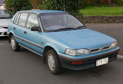
Image source: Wikimedia Commons
We need not spend a lot of time on this vehicle and its overheating problem, but it is nevertheless worth pointing out that when this writer arrived on the scene, the young technician had been poking around the overheating engine for several hours without a resolution in sight. This, even though the young tech did have a wiring diagram available- albeit a diagram that had been converted from its original SAE format into the European DIN format, which made no sense to the young technician.
Nonetheless, while the vehicle shown above was a Toyota product branded as a Holden Nova and therefore, familiar to the young technician, the imported version he was struggling with was branded as a Toyota Tazz, which was a hugely popular Toyota model in Southern Africa and some parts of Asia. Some other designations included the names Starlet, Corolla, Conquest, and Geo Prizm (and others) in various markets, and while most of these models had engines ranging from 1.4L to 1.8L, this particular imported Tazz had a 1.3L 12-valve engine the young tech had never seen before.
This writer had gained extensive experience on this engine during a long-ish stint working in Southern Africa, during which time he had come to know the 1.3L engine not only as hugely popular but also as hugely reliable, extremely fuel-efficient (despite being carbureted), as well as cheap and easy to repair. For those that are interested (and for possible future reference), the image below shows some detail of this engine, which in Toyota-speak, is the 2E engine-
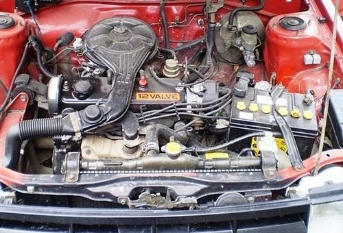
Image source: Wikimedia Commons (Public Domain)
In the case of the imported Tazz, the problem was that the electric radiator fan came on late, rotated too slowly, and only stayed on for a few seconds at a time. As might be expected, this caused the engine’s temperature to rise to well above the “NORMAL” mark on the temperature gauge in slow traffic or when idling at traffic lights. However, while (according to the customer) the engine's temperature had not yet risen into the upper 25 per cent of the gauge, a persistently high engine temperature is one of the very few things that can destroy this tough little engine.
Long story short, though: this particular problem is easily resolved simply by replacing the radiator fan switch, which is located on the thermostat housing, which is in its turn, located below the distributor. However, this engine uses two radiator fan switches; one active switch, and one standby switch- both of which supply a ground to complete a low-amperage circuit that energises the relay that powers the radiator fan. However, upon inspection, it turned out that a) the standby fan switch had been removed and the hole plugged by unknown persons, and b) that a replacement active switch was not readily available in Australia because this engine was not officially sold in Australia.
To his credit, the young technician had come to the (correct) conclusion that the fan switch was not supplying a proper ground, and since the correct switch was not immediately available, the young tech obtained the customer’s permission to make suitable modifications to the system to make the radiator fan work properly. The proposed modification involved finding a fan switch that a) fitted the threads in the thermostat housing (and operated in the same heat range), removing the radiator fan relay from the fuse box in the engine bay, and rigging up an aftermarket relay directly through the battery.
Again, long story short; it turned out that while this plan worked, it worked in reverse. The fan started as soon as the ignition was turned on, and ran continuously until the thermostat opened, at which point the radiator fan stopped working. It was also at this point that the young tech gave up, and called for help.
In a practical sense, the problem should not have been that difficult to figure out, but the young tech was a) faced with an engine he had never seen before, and b), was trying to relate the problem to a wiring diagram that he could not decipher. As an exercise in automotive wiring, the aftermarket relay was installed very neatly with no non-factory wiring showing, but the problem was obvious; instead of using a normally open switch that supplied a ground connection to the relay when it heated up, he had used a normally closed switch that supplied a ground connection when it was cold. Thus, in this case, the relay was supplied with a ground when the engine was cold, and when the switch heated up its contacts opened, thereby breaking the ground connection to the relay.
Replacing the fan switch with a normally open version solved the problem, and while the customer was happy, the young tech was somewhat embarrassed by the fact that he could not figure out a relatively simple problem by himself. In an attempt to explain his experience of the problem, he produced the DIN wiring diagram (he had bought online) and tried to point out where he thought the diagram was wrong, but all he managed to do was to confuse himself even more.
If you are not an expert auto-electrician, you may wonder what a DIN wiring diagram is, and why the young tech had thought it was wrong or confusing. Sadly, we cannot reproduce the actual DIN diagram the young tech had purchased here, but we can a) look at another example, and b) discuss some of the most important differences between DIN and SAE diagrams. Let us start with this question-
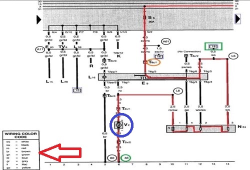
Image source: https://www.vehicleservicepros.com/service-repair/diagnostics-and-drivability/article/21236478/delving-into-din
This example of a DIN wiring diagram shows the path of current flow through an internal blower motor circuit in a late 1990s VW Jetta. This example can be referenced to illustrate some of the points below.
As a practical matter, “DIN” stands for Deutsches Institut für Normung e.V. This is an organization in Europe (Germany in particular), that draws up standards for anything from domestic electrical circuits, electrical appliances, tools, to automotive diagnostic equipment and much else besides such as, the dimensions of automotive radios and CD players and how relay terminals are numbered. In terms of how it operates, the Deutsches Institut für Normung e.V is the European equivalent of the SAE (Society of Automotive Engineers) that draws up and maintains standards in the US automotive market.
However, while both DIN and SAE wiring diagrams provide the same information, there are important differences between how SAE and DIN wiring diagrams present the information. For instance, car manufacturers using the SAE format to render wiring diagrams have considerable leeway in how they identify conductors, wire terminations, and components. By way of contrast, European legislation requires all car manufacturers to identify/label conductors, wire terminations, and components in the same way by using the same symbols and alphanumerical codes to identify the same item on all diagrams.
Moreover, the single biggest difference between SAE and DIN diagrams is that SAE diagrams are not required to indicate the direction of current flow through any circuit(s). Therefore, in practice, if you are trying to find a break in a circuit, the only clue about current flow on an SAE diagram is often only the orientation(s) of symbols that indicate diodes.
By way of contrast, current flow in DIN diagrams is always “downwards”, meaning that current always flows from the top of the page to the bottom of the page. This is a legal requirement that all compilers of DIN wiring diagrams have to observe, but the practical effect of this law is that you never have to guess in which direction the current flows through a circuit drawn according to DIN standards.
Let us look at some details of the section of the DIN circuit shown above. The details of the problem with the blower motor are not relevant here; but in the above example, the unbroken red line represents the “track” that the current follows through in the vehicles’ electrical system-
Thus, in the above example, all the components the current flows through are labelled in the same way, regardless of the vehicle make and model. As stated elsewhere, this is a legal requirement, so let us look at some examples of how components and wiring are labelled-
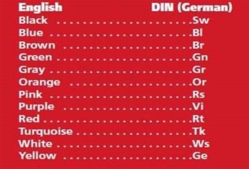
Image source: https://www.vehicleservicepros.com/service-repair/diagnostics-and-drivability/article/21236478/delving-into-din
Unlike SAE diagrams that do not always come with a legend that lists all the colours of all wires used in the diagram/circuit, European law also requires DIN diagrams to include a legend that a), lists all the colours of all the wires in the diagram/circuit, and b) that provides a translation of the colours into English. For instance, in this example, “Rt” stands for “ROT” in German, which translates into RED in English. Similarly, “Sw” stands for “SCHWARZ“ in German, which translates into BLACK in English.
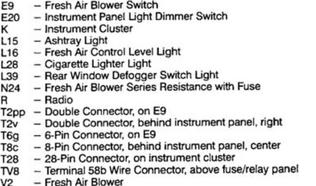
Image source: https://www.vehicleservicepros.com/service-repair/diagnostics-and-drivability/article/21236478/delving-into-din
In the context of DIN wiring diagrams, “wire termination” refers to the part or component where a particular wire ends or “terminates”, and not to the type of terminal that is crimped onto the end of the wire. As a practical matter, this can be hugely helpful because the termination label not only often identifies the type of circuit you are investigating; but labels that identify terminations that perform the same function on all European vehicles must also be the same on all DIN diagrams- regardless of the vehicle make or model.
The list of terminations above shows some examples, but on a more practical level, this legal obligation includes the following requirements-
There are far too many other examples to list here, but we are sure you get the point- all wiring terminations must be the same on all European vehicles, which is not the case with diagrams that follow SAE standards.
On most SAE wiring diagrams, components like motors will be indicated and named directly on the diagram. For instance, a motor symbol on an SAE diagram might be labelled as an internal blower motor, window regulator motor, seat adjustment motor or even as a motor that adjusts a side-view mirror.
However, things are a little different on DIN diagrams. For instance, while motors are all still indicated, all motors are simply labelled as DC motors, and without descriptions of what they do. Nonetheless, all motors are identified by alphanumeric codes both in the diagram and in a legend that must be printed on all parts/sections/pages of the diagram.
On the example DIN diagram shown here, the blower motor (circled in blue) on the problem Jetta is indicated by a motor symbol, and the alphanumeric code “V2”. So if you don’t know what the “V2” designation means, you can simply look it up in the legend, but the best part of this arrangement is that the internal blower motors in all European vehicles will always be indicated by the “V2” code. Similarly, all seat adjustment motors on all European vehicles will always have the same code, and all mirror adjustment motors on say, the drivers’ side on all European vehicles will also always have the same code.
This is a great way to remove confusion and guesswork from the process of analysing a circuit on a DIN wiring diagram. Moreover, where connections (on DC motors) are not included in pre-formed electrical connectors, the power inputs on all motors will always be labelled "30" (battery power), and all ground connections on all motors will always be labelled “31” (battery ground).
In addition, if the ground connection of a component is one of many ground connections that are grouped in one location, DIN diagrams must not only indicate the actual position of any particular ground connection in the grouping, but also the location of the group of connections. In the example DIN diagram shown above, this is shown at the bottom of the image: the blower motor’s ground connection is number 6, and the group of connections is located behind the instrument cluster on VAG-group vehicles, as shown by the “33” in the green circle.
This last point is particularly relevant since uniform labelling reduces, if not eliminates the possibility of testing circuits incorrectly. For example, if you know which connection does what, it becomes a whole lot easier to determine if the circuit under investigation is a pull-up or a pull-down circuit. Put differently, this means it is easier to determine if a particular circuit is controlled by battery power or by battery ground.
This principle also applies to switches on DIN wiring diagrams, and had the young tech known that, or could extract that knowledge from the DIN diagram, he would have had an easy way to determine if the radiator fan switch he had installed on the imported Toyota Tazz was normally closed or normally open, which leaves us with this-
There is no doubt that the ability to decode wiring diagrams is one of the most important skills any technician can acquire, but we also know that the way SAE diagrams are presented often makes it extremely difficult to follow a particular circuit. In most cases, it is almost impossible to relate the schematics of an SAE diagram to actual components on a vehicle because the layout of the diagram seems to have more to do with attempts to draw as many lines and symbols as possible into as small a space as possible, than with a logical presentation of the vehicle’s circuitry.
While DIN diagrams largely avoid this very annoying and confusing feature of SAE diagrams, it would be a mistake to underestimate the complexity of a complete DIN diagram. However, while the example of a DIN diagram shown in this article is only a tiny fraction of the complete diagram, following a circuit on a larger section becomes vastly easier when one thinks of DIN diagrams as track diagrams or even as current flow diagrams.
Instead of the chaotic arrangement of circuits on SAE diagrams in which it is seldom possible to be sure about the direction of current flows, current in DIN diagrams always flows downwards in largely parallel tracks in an arrangement that removes at least 95 per cent of the difficulty in following a particular circuit on any DIN wiring diagram.
Sadly, though, while the wiring diagrams for all European vehicles are legally required to be in the DIN format, very few manufacturers of vehicles made in other markets have gone to the trouble of converting their SAE wiring diagrams into the DIN format, or at least, making a DIN version available.
Despite that though, the next time you come across an electrical issue on a European vehicle, do yourself a favour and study its wiring diagram in DIN format before deciding that you’d rather not leave your comfort zone- you might just be surprised at how easy DIN wiring diagrams make it to relate circuits drawn on paper to actual components in vehicles.