While both CAN (Controller Area Network) and LIN (Local Interconnected Network) serial communications networks have served the auto industry well for many years, these systems are no longer able to control/monitor, and communicate effectively between the ever-increasing numbers of microcontrollers in modern vehicles. Advances in control and management systems that utilise multiple sensors and several electronically controlled actuators now require a degree of synchronisation that traditional serial communications systems can no longer provide. This article will discuss the FlexRay™ serial communications protocol, the first generation of which has been shown to increase both the speed, and efficiency of communication between multiple, high-end microcontrollers. Let us start with this question-
Put simply, FlexRay™ is an embedded serial communication system that uses time-synchronised exchange of data both to increase the speed of communication between microcontrollers, and to prevent the corruption of data on any given network within the greater communication system.
However, it must be noted that due to the high cost of FlexRay™ systems as compared to CAN and LIN-based systems, the first iteration of the FlexRay™ system will not immediately replace existing communication systems. Nonetheless, the existing FlexRay™ systems have gone a long way towards improving the management of critical safety and engine management systems, but it is expected that future generations of vehicles will make exclusive use of FlexRay™ technology. Below are some details of how the various communications systems are used in the current generation of vehicles-
LIN- based systems
These systems are currently used for low-speed communication between body components such as power seats, power windows, power mirrors, and other accessories. LIN-based systems typically use one wire between all implicated controllers and the rate of data exchange is usually limited to about 40 kilobytes/second.
CAN- based systems
CAN-based systems typically use two wires, or channels for mainstream communication between the microcontrollers that manage the ABS, transmission and other powertrain control functions. Note though that while the average communication speed on CAN systems is around 1 megabyte/second, up to five separate CAN systems may be required on some applications merely to manage the powertrain and ABS system.
FlexRay™- based systems
Since FlexRay™ systems can communicate at speeds of at least 10 megabytes/second over up to 4 channels, these systems have found an application in high-performance engine management systems, adaptive cruise control, drive-by-wire steering and throttle control, and active suspension systems, all of which have high data exchange requirements.
While the finer technical aspects of the FlexRay™ system may be of interest to automotive engineers and software programmers, it is important that we as professional technicians have at least a working knowledge of the technology, so what follows is a somewhat simplified explanation of the core concepts of FlexRay™ technology, starting with this question-
Although the current iteration of the technology uses only one pair of twisted, unshielded cabling between nodes to keep costs down, future iterations will use two channels (using two pairs of twisted wires) to accommodate increases in the complexity of control and safety systems. As a practical matter, differential signalling on a pair of wires is an effective measure against electronic noise induced by other systems without the need for expensive shielding of the wires. In addition to the pair of signal wires, FlexRay™ nodes are also provided with dedicated power and ground wires to power transceivers and microprocessors.
The practical advantage of FlexRay™ technology is that it offers both increased bandwidth and fault tolerance, but in some configurations, the system requires suitable termination in the form of a suitable resistor between the ends of the signal wires to prevent data leakage and signal noise. While typical FlexRay™ cabling pairs have an impedance of between 80 and 110 Ohms, this impedance can vary significantly between specific network layouts and configurations. Therefore, each implementation requires termination that is specifically designed and/or rated for that particular application, which from our perspective as technicians, might produce unpredictable results when the termination resistor fails, which brings us to the-
NOTE: The following diagrams are intended for informational purpose only, and are therefore not drawn to scale. Boxes labelled “ECU” are meant to represent any microprocessor or microcontroller that is, or can be included in a particular FlexRay™ layout or configuration.
It should also be noted that from our perspective as technicians that will have to diagnose issues in FlexRay™ systems, the single most important thing that sets FlexRay™ apart from other serial communication systems is the fact that unlike CAN and LIN – based systems, FlexRay™ systems can support layouts and configurations that other systems cannot. While selecting the most appropriate FlexRay™ layout or configuration to suit any given vehicle is the preserve of automotive engineers, we as technicians should be aware that the actual layout would largely determine how we approach a diagnostic problem. Below are some details on the possible layouts you might encounter in a modern vehicle-
Multi-drop Bus
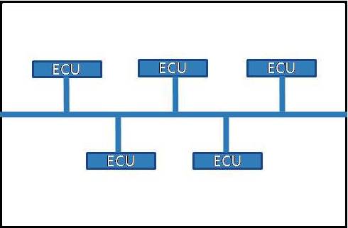
This is the simplest of the possible FlexRay™ configurations, and is largely similar to CAN and LIN--based systems that use a single cable to connect multiple microprocessors together into a single network. Note though that is the only FlexRay™ configuration that requires suitable terminations between the ends of the signal wires to prevent signal noises and/or reflections.
Like CAN and LIN-based systems, multi-drop bus FlexRay™ systems consist of a central “trunk” line from which short “branches” can extend to associated controllers. This configuration makes it easy to incorporate a multi-drop network into existing wiring harnesses that typically, use a similar topology. However, while this layout increases communication speeds by a factor of at least ten and significantly reduces wiring complexity over conventional CAN-based systems, the biggest drawback of this layout is that it is dependent on the correct termination being used. The wrong termination can cause either signal noise, or prevent controllers on the system from communicating at all.
Star Network
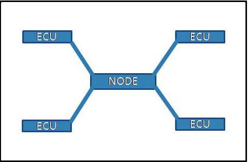
The primary features of FlexRay™ star networks is that it allows individual links, or controllers to be connected to a central node, in much the same way that a hub connects to individual ethernet controllers in a PC. Other advantages of star networks are that each individual link can be physically further away from the active node than is possible with multi-drop layouts, and that the system can continue to operate should one or more individual links fail.
Hybrid Network
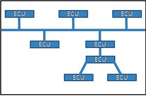
By combining the other two layouts, the resulting hybrid network offers performance, cost benefits, and reliability that neither multi-drop nor star networks can provide on their own. However, with hybrid FlexRay™ configurations there is no single layout that will answer the needs of all applications, meaning that each application will have a hybrid system that is unique to that application, which brings us to -
Unlike CAN-based protocols that use a system of arbitration to determine which controller gets to write data to the bus first based on the priority level of the message, the FlexRay™ protocol is based on the fact that each controller in a network is synchronised to a central clock. In practice, this means that each controller in a FlexRay™ network has a predetermined time slot in which to write data to the network, thus eliminating congestion and the possibility that data from one controller can be overwritten by data from another controller. In practice, when a controller misses its allocated time slot to add data to the network for whatever reason, it won’t get another opportunity to add data to the network until its next allocated time slot rolls around.
However, while CAN-based systems only need to know the baud rate* of the network as a whole in order for any controller to write data to the network, all the controllers in a FlexRay™ network need to know exactly how all other controller and nodes are configured in order for effective communication to take place on the network.
* The baud rate of a communication system is the maximum rate at which communication can be exchanged on that system. For instance, if a communication system has a maximum baud rate of say, 4 800, it means that 4 800 distinct signalling events per second can be exchanged on that system. This should not be confused with the bit rate; for example, if the information is exchanged in single bytes and the baud rate is 1, the baud and byte rates are identical. If however, the information were exchanged in bundles of ten bytes, the effective baud rate of the system would be 480.
The above explains why all the controllers in a FlexRay™ network have to know how all other nodes and controllers are configured. Some standard baud rates for serial communication systems are 110, 300, 600, 1 200, 2 400, 4 800, 9 600, 14 400, 19 200, 38 400, 57 600, 115 200, 128 000, 256 000 bytes per second. While baud rates of FlexRay™ systems in some automotive applications may deviate from these standards, all the controllers in any given network must be configured to the same baud rate for the system to work, which brings us to-
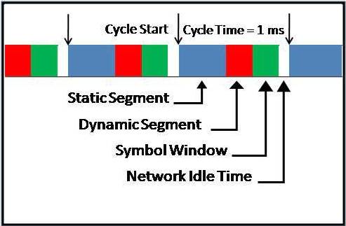
It should be noted that FlexRay™ signalling is a hugely complex subject, and a comprehensive discussion of all the details will fill several volumes. Thus, to remain within the scope of this article we will only discuss the main structure of a typical FlexRay™ signal, a representation of which is given in the diagram below.
Static segment
In an actual FlexRay™ signal cycle, the static segment is dedicated to the scheduling of specific, time-controlled/triggered data frames. In practice, this segment can be subdivided into several dozen “slots”, each of which contains a reserved frame, or set of data. In this context, “reserved” refers to data that is managed by a particular ECU, and that ECU can only write or transmit data into its reserved slot when its dedicated slot occurs in time. If the ECU misses its opportunity to transmit data in its reserved slot, it must wait its turn until its next reserved slot occurs in the subsequent signal cycle.
Since the position of each reserved slot is known in time, the data transmitted in these slots is said to be deterministic, which means that every controller in the network knows exactly how old the data in each slot is. The practical advantage of this scheme is that the accuracy of control loops that depend on consistently timed/spaced data can be greatly improved.
Dynamic segment
To prevent aFlexRay™ network from being slowed down by an excessive number of slots in the static segment, the dynamic segment allows for the occasional transmission of data that falls outside of the deterministic scheme. However, unlike the static segment that can be of different lengths, depending on the characteristics of the network, the dynamic segment has a fixed length, meaning that the amount of data this segment can cope with is limited.
The dynamic segment is sub-divided into one microsecond-long “mini slots”, and their position within the dynamic segment depends on the data each contains. For instance, mini slots that contain high priority data are allocated positions closer to the start of the dynamic segment than are mini slots that contain lower-priority data. If, as is the case with the static segment the ECU misses its opportunity to transmit data in its reserved mini slot, it must wait its turn until its next reserved mini slot occurs. In practice, the dynamic segment functions in a manner that is analogous to how CAN-based signalling works, in the sense that the transmission of high priority data takes precedence over the transmission low priority data.
Symbol window
The primary functions of the symbol window include maintenance of the signal cycle, and the identification and verification of cold start cycles. Note that in this context, “cold start” refers to the signals that are used to “wake up” the network, in manner that is roughly analogous to how a PC is woken up after a period of hibernation. In practice though, the symbol window does not generally receive or transmit data that is used for high-end vehicle control functions.
Network Idle Time
Represented in white, this segment has a known, predetermined, and fixed length, and all implicated ECU’s know what this length is. In practice, this segment does not receive or transmit data, but all implicated ECU’s and nodes use this segment both for time-keeping purposes, and to make corrections for any drift from fixed timings that may have developed over previous signalling cycles, but with particular reference to the immediately preceding signal cycle.
Based on the fact that FlexRay™ technology represents a new standard in high-speed, fault tolerant serial communication for automotive applications, there is no doubt that FlexRay™ technology will become more prevalent over the next few years. When it does, we may have to rethink the way we approach diagnostic procedures in general, and the diagnosis of failures of major electronic systems/components in particular.