The 4.3L V6 and two V8's of 5.3L and 6.2L displacement, respectively, that constitute General Motor’s Ecotech3 family of GDI (Gasoline Direct Injection) engines are not exactly new, and having been introduced into some GM trucks and SUV's in 2014, many of these engines will likely have accrued enough mileage by now to start requiring major servicing and /or repairs. However, GM has developed many new technologies, such as for instance, a split fuel system to make direct fuel injection work on these particular engines, and while these fuel systems work well enough most of the time, diagnosing, servicing, or repairing them can be challenging.
Thus, in this article, we will take a closer look not only at what makes these engines run, but also at some diagnostic/repair tips and tricks that will ensure effective repairs, and by extension, eliminate comebacks and unhappy customers, which is sometimes not an easy thing to do with this particular family of engines. Let us start by asking this question-
Apart from direct fuel injection to replace port fuel injection on the Vortec range of engines the EcoTec3 family of engines was designed to replace, the three versions of the EcoTec3 range all feature major architectural improvements over their predecessors.
For instance, swapping the intake and exhaust valves around makes room to angle the sparkplug more towards the centre of the combustion chamber, which in combination with specially designed pistons that contain most of the volume of the combustion chamber, improves combustion significantly. Also, direct fuel injection made it possible to raise compression ratios to 11:1 without creating knock, which increases engine life and reduces emissions while increasing power, at the same time. According to official GM sources, the combination of design changes that include cylinder deactivation under low engine load conditions and direct fuel injection has made it possible to reduce cold-start emissions by about 25%, which begs the question of-
While the EcoTec3 engines boast several new technologies that combine to produce engines that are particularly well-suited to towing, carrying heavy loads, and generally performing grunt work, these engines are also prone to issues that often require creative approaches to diagnostics, servicing, and repairs. Hard-starting conditions, no-start conditions, illuminated warning lights, and serious drivability issues that involve the fuel system are the most common problems, but other problems like oil dilution, fuel leaks, limp-modes, and varying degrees of power loss under some operating conditions also feature prominently.
From a diagnostic perspective, all of the above issues almost always involve some aspect of the fuel system, which comes in separate low-, and high-pressure parts on each vehicle, or fuel injector issues as the result of long use, or as the result of long use combined with poor fuel quality and/or poor service/maintenance practices.
However, the above is saying a lot, and since the devil always lives in the details we will break the fuel system up into its parts, and discuss the characteristics, features, and issues of each part separately, because understanding how each system works is important in terms of diagnostics, repairs, and particularly in avoiding personal injuries. Let us start with-
The low-pressure fuel system moves fuel from the fuel tank to supply the high-pressure system with enough fuel to satisfy the engine’s demand for fuel under all operating conditions. To do this, the low-pressure fuel system uses an MRA (Modular Reservoir Assembly) that contains an electronically controlled fuel pump, fuel pressure regulator, fuel filter assembly, fuel level sender unit, and a jet pump*.
* “Jet pump” in this context is a small pump that diverts some of the main (low-pressure) fuel pump’s output to maintain an adequate fuel level in the MRA under all operating conditions and fuel pump speeds.
In terms of operation, the low-pressure fuel system is monitored and controlled by the ECU, which controls a dedicated low-pressure fuel pressure control module. As a practical matter, the ECU requests low-pressure fuel from the low-pressure fuel pressure control module via the GMLAN serial communications system that links the UEC to the low-pressure fuel control module.
Based on the demand, the low-pressure fuel control module activates and controls the speed of the low-pressure pump with a 25 kHz pulse width modulated signal, to control both fuel pressure and volume, but note that the maximum current that can be supplied to the fuel pump is 22 Ampere, thus limiting the speed of the low-pressure fuel pump. The actual low-pressure value is transmitted to the ECU by the low-pressure fuel control module via a (serviceable) three-wire, pressure-sensitive sensor that is supplied with a 5-volt reference voltage by the ECU.
Although the low-pressure fuel system’s pressure varies with load, this system will typically generate pressures of between 43 psi and about 45 psi at idle, while KOEO (Key On Engine Off) values will typically fall into the 50 psi to 100 psi range, depending on operating conditions and factors such as the ambient temperature, among others. Cranking before a cold start-up will typically produce pressures of between 90 psi and 100 psi, but note that low fuel-pressure values during normal engine operation can fluctuate wildly as a function of constantly changing fuel demands.
Low-pressure fuel system issues
The low-pressure fuel control module can set and store fault codes, all of which will illuminate warning lights. Nonetheless, typical low-pressure fault codes relate to wiring issues as the result of abnormal voltages, currents, and/or resistances, with the most common cause of such issues being water ingress into the low-pressure fuel control module and/or its electrical connector. This is a major cause of frequent and unexpected stalling, and hard-, and/or no-start conditions, meaning that checking this module and its associated circuits should always be the first step in any diagnostic procedure aimed at resolving fuel system issues.
Note also that (new) replacement low-pressure fuel control modules are delivered blank, and must therefore be programmed before they will work. However, since the required software is usually not available to independents from official GM sources, you may need to purchase a subscription or membership from a third-party vendor to access it.
NOTE: Note that other causes of stalling and/or no starts could include either a factory-installed MRA that contains an incorrect/defective fuel pressure regulator, or a substandard aftermarket MRA that does not contain a jet pump. In the latter case, this means that the low-pressure fuel pump could run out of fuel under some conditions, such as when the fuel level in the tank is low, or when the vehicle is not on level terrain.
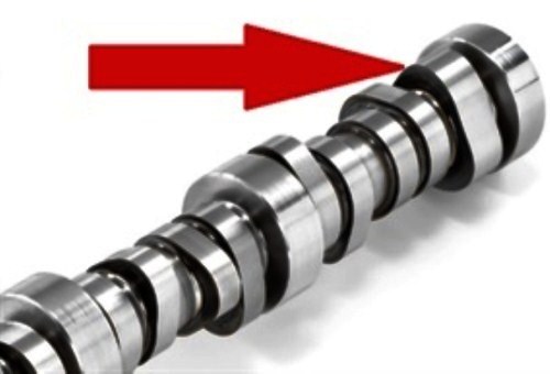
Image source: https://images.autoserviceprofessional.com/post/M-Photo-8-1.jpg
The image above shows the three-lobed cam on the camshaft of an EcoTec3 engine, which is the mechanism that drives the high-pressure fuel pump on these engines.
This system can produce a maximum fuel pressure of 3 118 psi, but during normal engine operation the fuel pressure is maintained in a wide range of pressures that fall between about 290 psi on the lower end, and about 2 176 psi on the upper end. Note that the actual pressure in the high-pressure fuel system at any given point in time is dictated by the engine speed and load, and that excess pressure in the high-pressure fuel system is relieved by a pressure relief solenoid that is controlled by the ECU with a pulse width modulated 12-volt signal*.
*Note that the condition of this circuit is critical for correct high-pressure fuel system operation. Any corrosion or other causes of abnormal resistances in this circuit can cause permanent low fuel pressure issues. Therefore, diagnostic processes for any high-pressure fuel pressure issues should ideally start with a thorough visual inspection and subsequent testing of this circuit. Note however that repairing the wiring in this circuit is never as effective over the long term as replacing damaged/corroded wiring is.
Based on the desired fuel pressure, the ECU opens the fuel pressure relief solenoid every time a lobe on the camshaft acts upon the pump’s plunger, so in practice, the ECU can match the actual fuel pressure with the desired fuel pressure three times per camshaft revolution. This is rather important because the duty cycles (pulse widths) of the fuel injectors cannot be adapted to control injection volumes. Instead, the ECU controls injection volumes by increasing injection pressures, meaning that an ability to “fine-tune” the fuel pressure three times per camshaft revolution translates into a more constant pressure in the fuel rails.
In terms of the system layout, the high-pressure fuel pump is bolted onto the engine with torque-to-yield bolts that must be replaced whenever the fuel pump is removed from the engine. Two stainless steel feed pipes connect the pump to the actual fuel rails, with the left-hand hand fuel rail containing the fuel rail pressure sensor. These sensors contain two analogue pressure sensors with two wires each, but note that they share a common 5-volt reference voltage.
Note that since the fuel rails do not feature a test port, the only way to monitor the actual fuel pressure is by monitoring live date from the fuel rail pressure sensor, which is serviceable, but note that replacing this sensor requires service information concerning torque settings if fuel leaks are to be avoided.
High-pressure fuel system issues
WARNING: Be aware that extreme care must be exercised when dealing with any high-pressure fuel system issues since residual pressure in the high-pressure side can be high enough to cause serious personal injuries. Therefore, residual pressure must be released strictly per service information guidelines before any service/repairs/maintenance is performed on the high-pressure fuel system.
Service information calls for the high-pressure fuel system’s fuse to be removed before starting the engine. While this measure is designed to allow the engine to run out of fuel, it is possible for the low-pressure fuel system on some vehicles to generate sufficient fuel pressure to keep the engine running as if it were in limp mode. Therefore, it is essential not to start work on the high-pressure fuel system until the actual pressure in the system falls below 100 psi, which can be checked/verified with a scan tool. If the fuel pressure remains above about 100 psi, you may have to disable the low-pressure fuel system as well.
The high-pressure fuel pump must be indexed before removal or installation
The high-pressure fuel pumps’ mounting flange is not designed to withstand the spring pressure that comes with the pump being stroked. Therefore, the three-lobed drive cam must be indexed to place the pumps’ plunger on the base-circle, and not on a lobe. Failure to index the engine properly could cause the mounting flange, to bend, deform, or even break when removing or installing the pump against spring pressure. Consult the relevant service information for the correct procedure to index the camshaft relative to the pump plunger, and be sure to replace the pumps’ torque-to-yield retaining bolts.
Fuel rail feed lines are strictly single-use
Note that the feed lines connecting the fuel pump and the fuel rails must be replaced every time they are disturbed. These lines are slightly deformed to allow positive automatic seals between the pump and the fuel rails when they are tightened down, which means that removing or disturbing the feed lines in any way destroys their sealing ability. Be aware that any attempt to re-use these feed lines will result in serious and dangerous fuel leaks.
Check TSB’s for vibration issues
Many Ecotec3 engines suffer from fuel leaks, and or/buzzing and/or loud clicking noises as the result of malfunctioning check valves or defective high-pressure fuel pumps. Several TSB’s describe the exact causes of these issues, but the point is that the only remedy for these kinds of issues is the replacement of the entire high-pressure fuel pump, mounting bolts, and feed lines and/or fuel rails.
Fuel pump driver-lobes may wear prematurely
This is a relatively common issue that involves increased or accelerated wear of the three-lobed cam that drives the high-pressure fuel pump, which causes severe mechanical noises and serious driveability issues as the result of perpetual low fuel pressure issues.
The primary causes of this issue include the use of incorrect or unsuitable engine oil, lack of regular servicing/oil changes, and running an Ecotec3 engine with low oil levels for extended periods. Note also that even if the driver cam is in perfect condition, not installing all the covers and sound-deadening material on the engine after a service or maintenance procedure could give rise to customers complaining of valve lifter-type noises, which brings us to-
Elsewhere in this article, we mentioned that fuel injection volumes are controlled through adaptations to the fuel pressure, but this fact along with very strenuous operating conditions and operating environments presented engine designers with a thorny issue.
The problem involves the fact that since the injectors can inject fuel only when the exhaust valves are closed, the time window for injections is only about 0.4 ms long, as opposed to the 1.5 to 3.5 ms that are common on port injection systems. Thus, designing injectors that can deal with high combustion pressures, as well as high combustion pressures and extremely high fuel pressures meant that the injector solenoid needed voltages that are higher than 12 volts to open.
To overcome this problem, engineers designed injector solenoids that could be opened with 65-volts impulses, but which could be kept open during an injection event with only 12 volts. The high opening voltages are created by a specially designed DC-to-DC converter in the ECU that uses dedicated capacitors to store injector-opening pulses.
It should be noted that due to the high demands that are placed on them, Ecotec3 injectors are not particularly long-lived and regular injector servicing/cleaning is required to keep these engine performing at their peak, but note the following-
Removing injectors requires special tools
For reasons that only become clear once you try to remove fuel injectors from an Ecotec engine, you need a special GM tool that applies an even pulling force over the entire fuel rail if you want to prevent damaging the injectors, the fuel rail, and the cylinder head. Note also that once the injectors are removed from the engine, the clips holding them to the fuel rail, all spacers, as well as all dust and combustion chamber seals must be replaced- as must be the fuel feed lines between the fuel rails and the high-pressure pump. All of these items are strictly single-use, and reusing any of them will result in fuel leaks.
Also, fitting new combustion seals not only requires the use of a special GM tool, but all newly fitted seals must be resized with yet another special GM tool to provide reliable and positive sealing between the injector and the cylinder head, which leaves us with this-
There is no doubt that the ECotec3 family of engines has several tangible advantages over their predecessors, but from a maintenance perspective, these engines present the average technician working for an independent workshop with some unique challenges.
One such challenge has to do with economics. For instance, does it always make financial sense to purchase expensive special tools on top of paying hefty subscription fees to obtain service information, given that you may not see an Ecotec3 engine all that often? We cannot answer this question one way or the other, but we thought it would be a good thing to give you some practical tips and advice on how to approach the fuel system issues on Ecotec3 engines, nonetheless.
