While many advances in the design, construction, and materials used in the internal combustion engine have made modern engines more efficient than they have ever been, all modern petrol engines are still only about 30% efficient. In practice, this means that about 70% of the energy that could potentially have been used to provide motive power to a vehicle is lost through friction, pumping losses, and parasitic power losses, but most importantly, as the result of waste heat. In this article, we will take a closer look at heat, or a lack of heat, as a cause of engine inefficiencies, as well as new developments in engine cooling systems aimed at improving the management of waste heat to improve fuel consumption and reduce emissions while improving engine performance, at the same time. Let us start with-
NOTE: While what follows might appear to be a digression from the main topic of this article, this digression is necessary to understand why car manufacturers are required to rethink the design and operation of engine cooling systems.
Since their invention, water-based engine cooling systems did nothing more than to maintain engine temperature within an acceptable range, but as we know, not all cooling system designs were up to the task in hot climates.
Moreover, until comparatively recently, all cooling systems worked in the same way, and all systems were prone to the same failures. We need not rehash the basics of engine cooling here, beyond saying that all of us have repaired engines that had overheated as the result of failed thermostats, failed fan and coolant temperature sensors and switches; failed fan motors and worn-out viscous fan clutches, and this writer's personal favourites*, burst radiator hoses, leaking radiators, and failed water pumps.
* Thinking back over a long career as both a technician and a workshop owner, this writer has often wondered why the flow of coolant in (relatively) modern engines was still controlled by a primitive thermostat when technologies such as variable valve and cam timing, multiple fuel injection events, and multiple sparking events under some conditions were becoming commonplace. It could perhaps be argued that since wax pellet thermostats are cheap to produce and work reasonably well, there was never a need to reinvent the proverbial wheel, but this is a debate for another time.
Nonetheless, while improved fuel and technologies such as the ones listed above have contributed greatly to the reduction of harmful exhaust emissions, the facts remain that a) modern internal combustion engines are still only about 30% efficient and b), that as a mechanical system, internal combustion engines have (almost) reached the end of their development potential. So, what does this have to do with primitive thermostats and outdated cooling systems designs?
You may well ask, because while technologies like variable valve/cam timing, multiple spark delivery, multiple injections, improved fuel quality, and advanced exhaust after-treatment systems can meet current Euro 6 emissions regulations (albeit just barely) these technologies will not meet the requirements of the next iteration of exhaust emissions regulations.
Essentially, car manufacturers are caught in a kind of Catch-22 situation. Several manufacturers are developing advanced and hugely expensive combustion control strategies, while others like Nissan and Mazda have produced (slightly less costly) technologies that improve combustion over a wide range of operating conditions. For instance, Nissan has produced a variable compression engine that is in current use, while Mazda’s SKYACTIV technology uses extremely high compression ratios to improve combustion. Mazda is also working on developing HCCI (Homogenous Charge Compression Ignition) engines that use even higher compression ratios to ignite petrol/air mixtures with compression alone under some operating conditions.
While these advanced technologies produce more power (than comparable engines in terms of displacement) while producing fewer emissions, the catch-22 situation arises from these facts-
Moreover, the facts also remain that combustion in a cold engine is poor and unstable, and that unstable combustion produces large volumes of emissions. As things stand now, the only way to combat poor combustion in a cold engine is to enrich the air/fuel mixture, which dramatically increases emissions until the catalytic converter is hot enough for the engine to enter closed-loop operation.
Therefore, car manufacturers are caught between the need to greatly decrease engine warm-up times to satisfy current emissions regulations, and the need to run engines hot enough to ensure stable combustion over the widest possible range of operating conditions without compromising engine durability.
If we take the conflicting requirements listed above and we add to them the facts that-
we begin to see that under some conditions*, some current cooling systems contribute to the formation of harmful exhaust emissions, which brings us to-
* When proposed new emissions testing methods soon become compulsory in most first-world markets, car manufacturers in these markets will be obliged to test their products under real-world driving conditions, as opposed to running emissions tests in laboratories under simulated driving conditions. We need not delve into the details of the proposed new emissions testing methods here, beyond saying that the new tests include the requirement to drive the vehicle on a public road when the engine is cold, which will necessarily have a significant impact on the total emissions load a vehicle produces during a test cycle.
There is no denying the fact that many modern 1000cc engines that are in current production produce as much, if not more power than the 1600cc and even 1800cc engines of twenty years ago, while using less fuel, to boot.
However, these power increases are the result of improvements in volumetric efficiency, which, in its turn, produce improved combustion. The downside of this, however, is that since increased combustion temperatures heat engines with compact dimensions rather quickly because there is a smaller mass to heat, much of the energy that is contained in the combustion process has to be shed to the atmosphere to prevent a compact engine from overheating quickly.
Let us put this in another way, and from an exhaust emissions control perspective. It has long been known that combustion is poor in cold engines, regardless of the engine’s dimensions and displacement, but despite this, engine designers have persisted in designing cooling systems that shed heat to the atmosphere somewhat efficiently, thus contributing to keeping engines cold for longer than is necessary.
Thus, while improving combustion reduces exhaust emissions though higher combustion temperatures that leave less fuel un-burnt, most cooling systems produce large fluctuations in the engine coolant’s temperature, which means that a cooling system can contribute to cyclical increases in exhaust emissions because the heating/cooling cycle sometimes cools the engine down to below the point where optimal combustion can occur*.
* In practice, cyclical increases in emissions are typically “cancelled” out by a catalytic converter when an engine is in closed-loop operation. However, if an engine reverts to open-loop operation for any reason, or takes longer than expected to reach closed-loop operation, sub-optimal combustion caused by an efficient (or sometimes, defective cooling system) can produce significant increases in several types of harmful emissions.
Somewhat belatedly, however, engine designers have come to realise that by making smaller engines that heat up faster (while retaining the basic function of a cooling system) it is possible to harness waste heat and to use that waste heat as a very efficient emissions control mechanism.
Therefore, instead of simply shedding waste heat to the atmosphere, cooling systems are now designed to have two functions. The first is to retain as much waste heat as possible after a cold start to establish stable combustion sooner, and the second is to shed as little heat as possible to keep the engine as hot as possible for as long as possible, while at the same time, not allowing the engine to overheat.
This might appear to be a tall order, but in practice, it turned out that it is possible to repurpose engine cooling systems without having to modify either engines or existing cooling systems components extensively. New cooling systems will still use radiators as heat exchangers, electrically operated fans to enhance airflow through heat exchangers, pumps to circulate coolant, and a mapped thermostat or a coolant flow control valve to regulate the flow of coolant through the system.
The only other major difference is in how new cooling systems will be controlled, so let us look at some of the major components we will soon start seeing in large numbers. Let us start with-
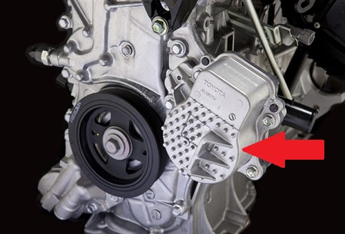
Image source: Toyota Media
This image shows the electric water pump on a Toyota engine, and while electric water pumps are not exactly a new invention, what follows will explain why electric water pumps will soon become the norm on new engines.
The (slightly simplified) laws of physics dictate that the rate of convection, i.e., the rate at which heat "spreads" through an object is determined by, among other things, the object's mass, structure, and density. In the case of modern internal combustion engines though, the rate at which any given engine heats up is not only determined by the overall mass of the engine and the principal material it's made from but also by -
NOTE: This discussion assumes that the engine is cold and that the conventional wax pellet thermostat is closed to prevent the circulation of the coolant.
From an emissions control perspective, this relationship is critically important because the bigger the volume of coolant in the cylinder and engine block, and the bigger the contact area between the engine and the coolant becomes, the longer it takes an engine to warm up. This might appear to be a self-evident truth, but the fact is that the relationship between surface area/coolant volume is less than ideal in many engines.
Thus, by using a water pump whose rotational speed is both infinitely variable and independent of engine speed, it becomes possible to adjust the coolant's rate of circulation to suit current operating conditions. For instance, if the thermostat is open, the electric water pump’s speed can be reduced to limit or slow down the coolant’s rate of circulation, which is not possible to do with belt-driven water pumps.
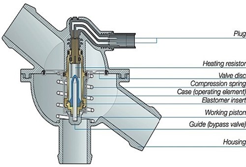
Image source: https://s19539.pcdn.co/wp-content/uploads/2016/09/Fig-21.jpg
This image shows a typical example of a mapped thermostat, or as they are also known, an electrically assisted thermostat.
As with electric water pumps, these thermostats have been in use for several years, but in most instances, mapped thermostats have been used in conjunction with conventional belt-driven water pumps. This has negated much of the inherent advantage of a computer-controlled thermostat because the flow rate of the coolant through the thermostat is not a function of the water pump’s speed, but a function of the speed of the engine, which drives the water pump at a fixed ratio via a drive belt.
Nonetheless, the biggest single advantage of a mapped thermostat is that its operation is not directly controlled or dictated by the temperature of the coolant. As we know, in a conventional thermostat, the increasing temperature of the coolant causes a wax pellet to expand, which then acts on a pushrod to open the built-in valve. While this works well to prevent an engine from overheating, the problem is that conventional thermostats are unable to control the coolant temperature precisely, because they stay open and closed for relatively long periods, which produces large fluctuations in the coolant temperature.
Mapped thermostats, on the other hand, are controlled by a dedicated control module that heats an electrical element that is built into the thermostat, based on input data from one or more dedicated coolant temperature sensors. Therefore, the actual opening of the thermostat’s valve can be controlled precisely to eliminate large fluctuations in the coolant’s temperature.
Thus, by using mapped thermostats in conjunction with other components such as an electric water pump whose speed can be regulated to increase or decrease the rate of coolant flow through an engine, it becomes easier to maintain an engine’s overall temperature at the level where combustion is the most stable over the widest possible range of operating conditions.
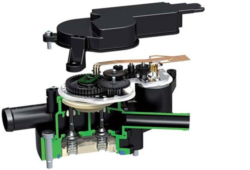
Image source: https://www.efiautomotive.com/wp-content/uploads/2019/08/module-actionneur-DC-low2-1.jpg
While coolant flow control valves such as the example shown here have been in use on hybrid vehicles for many years, they have not seen service on many conventional vehicles.
Nonetheless, the primary reason why flow control valves are used on hybrids is that cooling systems on hybrid vehicles typically consist of several sub-systems that have different cooling requirements. Sometimes, different cooling systems also use different types of coolant, and in these cases, one or more sub-systems have dedicated coolant pumps. However, in cases where one or more systems use the same type of coolant, all such systems are typically served by a single electric pump, but the distribution of coolant to different systems is always managed by a computer-controlled coolant flow control valve.
In their simplest form, coolant flow control valves contain two or more solenoid valves that can be opened and closed independently of each other. Thus, on a conventional vehicle, the water pump's output might be delivered to the flow control valve but depending on operating conditions, only a part of the flow might be diverted to the radiator, while the rest might be directed back into the engine's circulation pattern to maintain the engine's temperature.
Exactly how the coolant is flow distributed/redirected / blocked-off, or otherwise managed depends on the vehicle and current operating conditions. In all cases, though, the dedicated engine cooling control module uses input data from several coolant temperature and other sensors to manage the flow of coolant so that the engine's overall temperature is maintained within a range of two or three degrees to ensure stable combustion under all operating conditions.
We know that electric radiator fans are typically activated by a dedicated sensor that measures the coolant temperature in the radiator. While this approach works reasonably well, this method of fan control produces large temperature fluctuations in the coolant in different parts of the cooling system.
We also know that multiple-speed speed radiator fans have been common for many years. However, in new cooling system designs, the speed of the radiator fan(s) will not only be infinitely variable; the operation of the fans will be also be based on input data obtained from temperature sensors located in various parts of the cooling system, and not only in the radiator itself. In practice, the signal to the radiator fans will be pulse-width modulated to produce an infinite range of fan speeds, in much the same way that return-less fuel systems use the rotational speed of the fuel pump to regulate fuel pressure.
In practice, however, the duty cycles of radiator fans will be significantly shorter, and fans will almost certainly run at lower speeds more often than on old-style cooling systems since the burden of maintaining the engine temperature will no longer fall on the radiator alone. Assuming that all components, i.e., the electric water pump, mapped thermostat, and flow control valve work as designed, the volume of coolant that requires cooling at any given time will be smaller since most of the coolant needs to be kept at high temperatures to maintain the engine’s temperature.
Thus the primary task of the radiator and cooling fans is now to shed only excess heat, and not to shed as much heat as possible in the shortest possible time. The term “excess heat” however, is not precisely definable, since this will differ between engines designs and engine types. Other factors like ambient temperatures, local humidity, operating conditions, vehicle use, and driving style also feature in this equation, but these variables are accounted for in the temperature control modules’ monitoring /control algorithms and look-up tables.
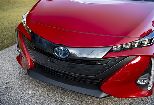
Image source: https://www.searchautoparts.com/sites/default/files/images/MA05%20-%20E8.jpg
Grille shutters like the ones on this 2020 Toyota Prius are also not new inventions and have for many years been in use on many vehicles in cold climates to reduce engine warm-up times. However, computer-controlled grille shutters will soon become standard equipment on all vehicles, and not only on hybrids and conventional vehicles used in cold climates. In practice, computer-controlled, adjustable grille shutters that work in conjunction with other strategies, such as active control over the rate of coolant flow offers one of the simplest, yet most effective ways to prevent excessive heat losses by limiting airflow over and through the radiator core, which leaves us with this-
At the risk of overstating the case, new-generation cooling systems are not only intended to limit waste heat losses on the one hand, but also to regulate the engines’ temperature more accurately, and within a narrower range than it was possible to do before, on the other.
From an emission control perspective, maintaining stable combustion through improved management of waste heat translates directly into fewer emissions under all or most operating conditions, which should please most regulatory bodies.
From our perspective as technicians, however, the requirement to maintain the engine’s temperature to within extremely narrow margins might present us with a rather steep learning curve in terms of a) identifying failure modes correctly, and b), confirming or eliminating component failure as the cause of an overheating problem. At the very least, we will need to learn or devise new tests, learn to interpret new types of oscilloscope traces correctly, and learn to draw correct and valid inferences from freeze-frame and other test data.
Moreover, despite a diligent online search, this writer could not find any meaningful technical information on any aspect of new cooling systems, apart from a few known good/bad oscilloscope traces of electrical water pumps on race cars that were at least five or six years old. What the lack of technical information means in practice, is that in markets where car manufacturers are not obliged to share technical information with non-dealership workshops, very little, if anything is known about how the interactions between several relatively simple components work in real-world driving conditions.
Thus, if we encounter a vehicle featuring a new generation cooling system with say, a seemingly defective radiator fan based on the owner’s observation that the fan hardly ever seems to run for more than a few seconds at a time, and there are no fault codes present, what are we to conclude? Do we conclude that fault codes have not set yet, or that the fan is working as designed? The latter will more likely be true but, in the real world, only time and the Mandatory Data Sharing Scheme will tell.