Coolant mapping and HFO 1234yf refrigerant are two technologies that are growing in popularity, especially in european vehicles. In this article we touch on some important considerations to take into account when servicing and repairing vehicles that are equipped with either.
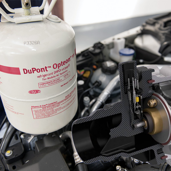
HFO 1234yf
This vehicle refrigerant has been the cause of many debates for some time now, more often than not in relation to its flammability. Some vehicle manufacturers have made the move to the ‘new’ refrigerant, whilst others have started using it and then reverted back to r134a.
Regardless of which side of the fence you personally sit on, servicing vehicles with HFO 1234yf is a reality.
One advantage of this refrigerant is that it has very similar chemical properties as r134a such as the boiling point and pressure/temperature relationships.
While the refrigerant requires a special oil and the o-ring and hose material has changed to some extent, the physical layout of the air conditioning system is the same.
The main differences being the strong preference to utilise a TX (Thermostatic Expansion) valve over an orifice tube system and variable stroke compressor as well as the suction and liquid lines going to the evaporator core being a single assembly. The logic behind this being that cooling the liquid before it reaches the TX valve results in better thermal efficiency. While we may have seen both strategies in r134a systems, they are proving far more common in HFO 1234yf systems.
So what are the main hurdles that workshops face in relation to this shift?
Different equipment required for servicing (AC charging/recovery machine and leak detector)
Increased cost of refrigerant (Compared to r134a)
Coolant mapping
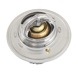
If you’re reading this, you’re no stranger to how a typical thermostat works. A system has proven reliable for many years. While manufacturers can fine-tune a thermostat to open at various different temperatures by changing the wax pellet and expansion material, it is essentially limited to three ‘states’:
Thermostat closed where the coolant remains in the engine and using the bypass circuit no coolant flows to the radiator.
Thermostat open where the coolant flows to the radiator to remove heat.
Thermostatic control range where the designed opening temperature of the thermostat is maintained.
The thermostatic control range set by the vehicle manufacturer will be dictated by a trade-off on emissions, fuel economy and performance.
For maximum performance, we generally want a lower operating temperature. This helps to reduce engine knock and optimise ignition timing, particularly under high load.
For optimum fuel economy and lower emissions, a higher temperature is generally best for partial throttle, stop and start type driving.
With a mapped thermostat, we are able to achieve both of these conditions without having to compromise.
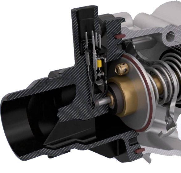
A mapped thermostat still uses a wax pellet to open itself as well as a spring to close, but it also utilises a small heating element inside the wax pellet that is generally controlled by the PCM.
The PCM may use an array of inputs including engine load, rpm and vehicle speed to alter the position of the thermostat.
So in this system, using our points above, if the wax pellet in a vehicle is set open at 100 degrees Celsius but the PCM notices the vehicle demonstrating high load and speed conditions, it will command the thermostat to open earlier to facilitate performance in these conditions. This is generally done by pulse-width-modulating the heater element. The greatly diversifies the range in which the thermostat can be controlled beyond those 3 of a typical thermostat.
If and when this system fails, the thermostat can still operate as per normal and generally one or more fault codes will be logged.
While the utilisation of mapped cooling system has been popular on European vehicles for a number of years now, it is starting to be seen more often from manufacturers of other regions.
It’s also worth mentioning, this is not the only strategy we have seen used to command more control over engine temperature. Systems utilising multiple valves and solenoids have been used in engines like Fords 1.6L EcoBoost as well as split systems in hybrids, parallel, cross and reverse flow coolant patterns.
We’ve seen exhaust manifolds incorporated into cylinder heads to speed up warm-up and reduce emissions (and save costs too we’re sure) as well as specifically designed plastic sleeves used by Toyota to reroute coolant to the cylinder block.
We suspect we will continue to see more electronics and finer control of existing engine systems into the future, primarily driven by regulators increasing pressure on vehicle manufacturers to meet ever more stringent emissions levels.
