Much has been written on the topic of how much safer a plethora of ADAS systems have made modern vehicles as compared to their predecessors, and this is in no small part because car manufacturers have for the past 15 years or so, spent more money, time, and effort on developing ADAS technologies than on any other area of development.
Much has also been written on the topic of how important correct ADAS system calibration is to ensure the proper operation of these systems, and the internet abounds with countless articles and “How to…” guides on how to perform these calibration procedures properly. However, what many, if not most such guides do not explain is that the foundation of all ADAS systems is something called “computer vision”, or CV for short.
Essentially, CV is a generic term for a collection of technologies that enable a modern vehicle to see or perceive its immediate surroundings. Thus, in this article, we will take a closer look at some of the principal technologies that allow a modern vehicle to perceive the world well enough through electronic eyes and ears to ensure that ADAS systems work as expected when required. Let us start with-

Before we get to the specifics of how ADAS cameras and sensors underpin the workings of ADAS systems, it is perhaps worth pointing out that cars don't "see" their environments in quite the same way that humans do. While this might seem like a self-evident truth, the fact is that a modern vehicle cannot stop itself from reversing into an object such as another vehicle in a crowded parking lot or a confined driveway based on the image we see on a display screen in the dashboard.
As a practical matter, the image we see displayed on a screen of what is behind a vehicle when we reverse is of absolutely no use to the vehicle or any of its ADAS systems. The images we see as the vehicle moves backward are presented purely for our benefit in a form and format that our brains can process. By way of contrast, the vehicle perceives or “sees” the area behind it in terms of algorithms that are processed by artificial neural networks that are constructed around a set of automotive industry standard “Common Objects in Context” datasets that are used to train artificial perception networks or systems.
In translation, the above means that when one or more Common Objects in Context (i.e., the context of a vehicle being in normal use) are detected by the reverse camera, the detected object(s) are converted into algorithms that categorise the objects. Such objects could be barriers or other vehicles in a parking lot, a garage door, bicycles, skateboards, or other toys scattered around a residential driveway. Nonetheless, once such common objects are detected and converted into algorithms, the information is processed by one or more artificial neural networks, which, in their simplest form, are networks of electronic circuits that (very roughly) imitate the way human brains process information.
Of course, artificial neural networks cannot think in the way humans do. These networks are only effective because they have been taught to recognise certain objects and to issue warnings or take certain actions based on how accurately they can categorise detected objects. So, while an artificial neural network can imitate some of the most basic functions of human brains, these networks also cannot make conscious choices. For instance, an artificial neural network cannot choose to sound an alarm when it detects an impending collision with a motorcycle behind the reversing vehicle but ignore a much smaller (but detectable) tricycle between itself and the motorcycle.
So, an artificial neural network in a reversing vehicle cannot allow a vehicle to crush a small but detectable object like a tricycle (with perhaps a small child riding) it but sound an alarm when it detects a larger object such as a stationary motorcycle behind the tricycle. In practice, these networks are taught by deep learning and/or machine learning techniques to recognise, categorise, and to react to all detectable objects in the reverse camera’s field of view.
Of course, how effectively artificial neural networks react to detected objects depends entirely on the quality of the input data they receive from cameras and other sensors, so let us look at some-
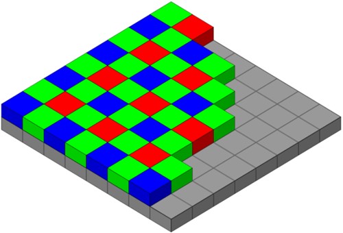
Image source: https://en.wikipedia.org/wiki/File:Bayer_pattern_on_sensor.svg
This image shows the basic construction of the light receptor (“receptor”, for want of a more descriptive term) of a typical commercially available digital camera, with the actual sensor/processor being represented by the grey structure and the filters being represented by the red, green, and blue squares overlaying the processor. Observant readers will notice that the green filters outnumber the red and blue filters.
The operating principles of such cameras are relatively simple. When light enters the camera, the incoming light passes through several convex and concave glass optical elements that refract or bend the light to cover the entire receptor and to strike the receptor at right angles, i.e., straight from the front.
As a practical matter, the number of filters, aka pixels in the receptor determines the size and resolution of the processed image. For instance, if the receptor has a stated resolution of 1920 by 1080 pixels, the receptor would contain approximately 500 000 red and blue filters, and approximately 1.5 million green filters, but note that this distribution largely depends on the manufacturer of the receptor. Nonetheless, as photons (light particles*) strike each filter element, each filter element “borrows” some of the characteristics of all the filters that adjoin it.
* Note that light consists of both solid particles and electromagnetic waves.
This process is known as "bayering", an extremely complex process that takes advantage of some of the properties of light , but we do need to delve into the complexities of this process here. In practice, though, "borrowing" some characteristics of adjoining filters makes it possible to create the colours in the images that digital cameras produce. We might mention that since green falls into the middle of the visible light spectrum, with red and blue on either side of green, it is easier to add either red or blue to green to create different colours than it is to add green to either blue or red to create different colours, which explains why green filters outnumber red and blue filters in ordinary digital cameras.
The earliest iterations of ADAS systems used optical cameras of the type described above but the biggest single disadvantage of such cameras is that they do not work well in low light conditions, such as in poorly-lit underground parking garages or at night. To overcome this limitation, design engineers have essentially redesigned digital cameras to make them more suitable for use in low light conditions, meaning that modern cameras meant for automotive use differ from "normal" digital cameras in several meaningful ways which include, but are not limited to the following-
Field of view
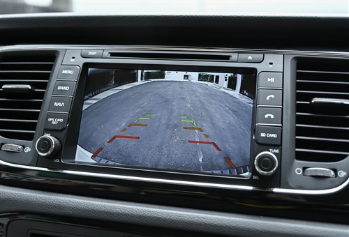
In the case of reverse cameras, engineers can now design and manufacture optical elements that produce wide-angle views. Typical wide-angle views now range from 179 degrees to about 185 degrees, both of which distort known straight lines into curved lines, such as in the example shown above. It is worth noting that in systems where the camera's field of view exceeds 180 degrees, the system can detect objects that are slightly ahead of the camera if these objects are a certain distance away from the vehicle. This ability is roughly analogous to some people's peripheral vision, which can detect objects slightly behind them while they are looking straight ahead.
Removal of green filters
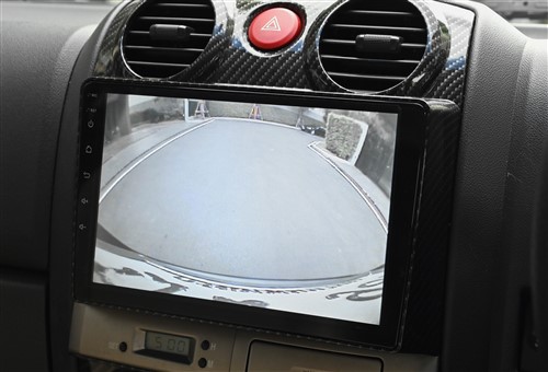
To make some cameras more suitable for use in low light conditions, design engineers have replaced the green filters with clear elements that have an increased sensitivity for low light conditions, and an increased resistance against electronic noise because the light receptor's gain does not have to be increased to high levels in low light conditions. Note that cameras with clear filters are denoted as RCCB cameras, with RCCB standing for Red-Clear-Clear-Blue [sensors].
The image shown above was taken with an RCCB camera during low ambient light conditions about an hour after sunset. Note that there is no green light in this image, and although the resolution of this image is not as high as it would have been had it been taken with a non-RCCB camera, the ADAS system that controls the reverse camera does not have to see pretty, high-resolution images. This system only needs approximate information of the area behind the vehicle, so this image was converted into a format that is visible to human vision purely for the driver’s benefit, which brings us to-
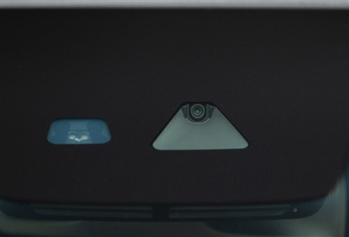
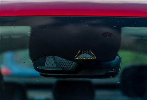
Forward-looking ADAS optical cameras come in two “flavours”; mono cameras, such as the example shown here, and stereo cameras, both of which we will discuss in some detail below. Let us start with-
Mono cameras
As their name suggests, mono cameras are single cameras mounted in a camera module and while early iterations of mono cameras only saw service in Lane Keep Assist systems and then only in bright light conditions, most modern mono cameras are used in a range of ADAS systems due to their vastly improved performance in low light conditions.
In practice, modern mono cameras can not only capture high-resolution images of the area in front of the vehicle, but their increased computing power can also detect and differentiate between various classes of objects. These include other vehicles, pedestrians, traffic lights, and most road signs- all of which were beyond the capabilities of early mono cameras that were essentially, miniaturized commercial digital cameras.
By way of contrast, modern mono cameras typically use CMOS (Complementary Metal Oxide Semiconductor) sensors that can best be described as “electronic eyes” in the form of extremely complex computer chips. In terms of operating principles, CMOS cameras use photodiodes (diodes that are sensitive to light) and a transistor switch for each photodiode.
When light strikes each photodiode, the intensity of the incoming light is converted into an electrical signal, which amplifies the light signal. Moreover, since each photosensitive diode has a dedicated transistor switch, it is possible to manipulate the matrix of switches in such a way that the light signal from each pixel in the light receptor can be accessed both individually and sequentially at a much higher speed than is possible to do in CCD (Charge Coupled Device) cameras. The advantage of this is that CMOS cameras "construct" images by adding one pixel at a time to a matrix, which greatly improves the image's resolution. Moreover, by using photodiodes, the electronic noise that occurs naturally during image processing is all but eliminated, which is the mechanism that increases the low-light ability of CMOS cameras.
As a matter of fact, CMOS cameras now underpin ADAS systems like Adaptive Cruise Control, Automatic Emergency Braking, Lane Keep Assist, and Pedestrian Automatic Emergency Braking- among several others. In this regard, it is worth noting that car manufacturers have developed mono ADAS cameras to the point where they can now detect and differentiate between objects like bicycles, pedestrians (including small children), street light poles, and many more.
It is worth noting that while these advanced abilities are not (yet) available on all new vehicles, Honda has recently managed to replace the radar transponder on some models with a mono CMOS camera and still have the same (or even improved) ADAS functionality in their Adaptive Cruise Control, Automatic Emergency Braking, Lane Keep Assist, and Pedestrian Automatic Emergency Braking ADAS systems.
Stereo cameras
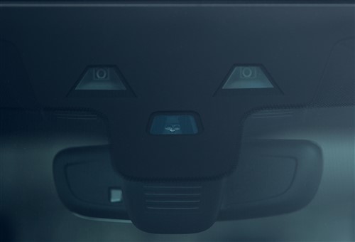
This image shows a pair of optical cameras located some distance apart in the camera module. These particular cameras have the same capabilities as modern mono cameras, but the advantage of using two cameras greatly increases the accuracy of various ADAS systems. Here is how stereo cameras work-
The two cameras work independently of each other but since the distance to an object is slightly different for each camera (as seen from each camera), the images each camera captures are compared to each other continuously so that the camera control module can calculate the distance to an object more accurately than is possible to do with a mono camera.
As a practical matter, this process is roughly analogous to how our brains use images from each of our eyes to create depth perception, which allows us to see that some objects are further away from us than others are. If we did not have depth perception, everything around us would appear to be at the same distance from us.
So, since cars do not have brains, stereo optical cameras use a branch of mathematics called epipolar geometry, in which the baseline is the distance between the two cameras. Since the two cameras are mounted in the same plane, and the distance between them is known, the difference(s) in the images each camera captures is used to triangulate the distance to an object within the cameras' combined field of view with great precision.
This information is shared between several ADAS systems. For instance, stereo cameras make it possible for an adaptive cruise control system to work without the need for a radar transponder, and progressively more vehicles are using stereo optical cameras to underpin ADAS systems such as obstacle and pedestrian avoidance- among others.
However, the single biggest advantage of stereo cameras is that they can create 3D images or maps, aka point clouds of the area in front of the vehicle that falls within the cameras'' combined field of view, which greatly enhances the functionality and accuracy of a vehicle's onboard navigation system. Moreover, the ability of these systems to measure distance is hugely important in the development of autonomous or self-driving vehicles since the distance to objects and other vehicles around such vehicles forms the basis upon which all driving decisions are made.
So even if we don't yet work on self-driving vehicles, many of the vehicles we do work on have stereo camera-based ADAS systems that depend on the proper calibration of the cameras to work as both designed and expected. Therefore, even if we don’t work on these or other ADAS systems directly, we have a responsibility not to do anything that could potentially disturb or upset the calibration of any ADAS system. Put differently, the guiding principle we should all follow concerning ADAS systems is “If it ain’t broke, don’t try to fix it”, which leaves us with just-
In the next and final instalment of this 2-part series, we will discuss the operation of other ADAS sensors. These include time-of-flight cameras, also known as LIDAR systems, as well as RADAR transponders, GPS/GNSS sensors, and various types of supersonic and acoustic sensors that use sound waves, as opposed to light waves, to measure distances to objects.