Many mechanics and technicians view automatic transmissions as finicky and overly complicated mechanisms that are difficult to diagnose, and even more difficult to repair, and would rather lose a repair job involving an automatic transmission than use the knowledge they already posses to figure out issues that are relatively easy to diagnose and repair, more often than not. If you have been avoiding working on automatic transmissions for whatever reason, this article will explain how you can do more automatic transmission repair jobs in-house, instead of passing them along to a competitor, so let us start with saying that-
At their cores, automatic transmissions have not changed much over the last thirty years or so: they still use the same components and pressurised fluid they did three decades ago, and they still work on the principle that if action “A” happens, action “B” must necessarily follow as a consequence of action “A” having been completed successfully. This is still the case today even in the most advanced transmission designs, and provided one keeps this guiding principle in mind, much of the mystery of how automatic transmissions work and why they fail, is removed.
However, what has changed by a great deal is how modern automatic transmissions are controlled, and it is in the area of control and management that most transmissions failures occur. Purely mechanical failures are relatively rare, and while they do occur, these failure modes are very often secondary to failures or malfunctions of modern transmission control systems.
What is also true is that the addition of torque converter lock-up clutches, up to four speeds (or ratios) above the three speeds that the oldest among us are used to, and several operating modes a driver can choose from has added several layers of complexity to modern automatic transmissions. Nonetheless, while the complexities of modern automatic transmissions have greatly improved the driving experience even in entry-level models over the past few decades, the basic operating principles of automatic transmissions have largely remained unchanged.
Having said all of the above, we should perhaps add that a); the correct operation of the hydraulic circuits inside an automatic transmission is entirely dependent on the correct operation of the many electrical circuits in a transmission control system and b), that neither the basic principles of electrical circuit design, nor the methods of testing electrical circuits have changed.
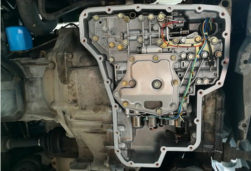
Thus, given the above, it should be possible (in theory, at least) for any competent mechanic to diagnose almost any fault on almost any automatic transmission, but things are not quite as simple as that. However, it is possible for most competent mechanics to diagnose a great many common issues on most automatic transmissions simply by using the knowledge they already have: knowledge they have gained by diagnosing other, unrelated systems and components, such as for instance, fuel injectors, so consider the image below, and ask yourself-
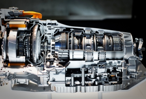
Of course, everyone sees some detail of the internals of a typical automatic transmission, but is this something you would rather not get involved with in a diagnostic sense, or is it something whose inner workings should be easy to figure out using the first principles of hydraulic and electric circuit design?
If your answer is “Not getting involved”, we hope to change your mind, but if your answer is “I’ll figure it out”, you should not have any difficulties with deciding where to draw a line between electrical and hydraulic causes of failures of, and/or malfunctions in, automatic transmissions.
Note though that the distinction between the two main causes of transmission failures and malfunctions is not always clear-cut, and in some cases, the better option is to refer the vehicle to a specialist repairer. Nonetheless, it has been this writer’s experience that many, if not most issues on automatic transmissions are easy to diagnose and repair* on the one hand, and that very few automatic transmission failures or malfunctions are serious enough to warrant a rebuild or replacement, on the other.
* Note that this only applies to transmissions that are actually serviceable in the sense that there is technical /service information available on the type, grade, and formulation of transmission fluid required, as well as on the quantity of fluid required, which information, as we all know, or should know, is generally not available for transmissions with so-called “life-time” fills.
Nevertheless, there are still millions of serviceable automatic transmissions in use today, so before we look at some practical examples of common automatic transmission issues and how to diagnose them, let us look at a typical-
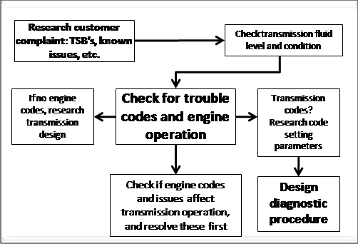
While the flow chart above is very rough approximation of a diagnostic process, the general pattern it represents should suffice to enable any reasonably competent mechanic to distinguish between electrical and hydraulic causes of automatic transmission issues. More to the point though, it should also enable most reasonably competent mechanics to decide where to draw the line between what is possible to repair in-house, and what is best left to a specialist repairer. Note that crossing this particular line can be very costly.
Before diving into specifics however, it is crucially important to keep two things in mind when diagnosing electrical issues on automatic transmissions, these things being the facts that-
Test lights are useless
While a simple 12-volt test light will indicate whether or not an electrical circuit is energised, a simple test light cannot be used to distinguish between current and voltage. It should be noted that current and voltage are not the same thing, so for those who have forgotten the difference between them, here it is again-
“Current” is defined as the rate at which an electrical charge flows past any point in an electrical circuit. “Voltage”, on the other hand, is defined as the potential difference in an electrical charge between any two points in an electrical circuit or field. In practice, this means that voltage can be described as the cause of say, a transmission shift solenoid cycling on and off, while current is the effect, or the speed with which the solenoid cycles on and off. The distinction is an important one, since transmission shift solenoids that are supplied with insufficient current can cause a wide variety of shifting issues.
The engine must be in perfect running condition
Since engine issues can, and do affect the operation of the transmission, all engine issues such as misfires, vacuum leaks, and abnormal fuel trim values (among others) must be resolved definitively before an attempt is made to diagnose any transmission issue. Always keep in mind the fact that about the only time a transmission will affect the operation of the engine is when the ECU has initiated a limp mode as the result of a (mostly mechanical) failure, defect, malfunction, or fault in a transmission with the object of the limp mode being to protect the transmission against sustaining further damage. In these cases however, the reason for the limp mode will almost certainly be indicated by one or more transmission fault codes.
You need up-to-date service information
Official repair manuals and other sources of technical information such as the professional versions of ALLDATA, Mitchell, and others can be valuable sources of diagnostic and/or repair information. However, these sources do not usually provide much, if any information about known issues on particular transmission models /designs, nor do they provide much, if any information on known fixes for these issues.
Since research is key to successfully diagnosing automatic transmission issues, this writer recommends specialist sources like the Automatic Transmission Rebuilders Association (ATRA), and the Automatic Transmission Service Group (ATSG). Both sources maintain a collection of websites, publications, and other resources some of which are free, while others require a subscription to gain access to TSB’s, discussion forums, technical articles, and How to- guides written by expert transmission technicians and rebuilders, which brings us to-
While it is true that automatic transmission repair is a specialist field, it is also true that dirty, contaminated, degraded, and unsuitable transmission fluid is by far the most common cause of transmission failures and malfunctions, although some automatic transmission designs are more resistant to the effects of degraded fluid than others are.
It is perhaps worth mentioning that transmission fluid performs two functions, these being to act as the medium of power transfer in the torque converter and elsewhere in the transmission, and to provide lubrication and cooling to moving parts in the transmission, at the same time. In practice, this means that many transmission malfunctions are the direct of either a loss of fluid pressure, or a loss of adequate lubrication.
Having said the above, let us look at two common issues, these issues being-
Shift solenoids stuck off / Shift solenoid circuit range and/or performance issues
These issues will always be indicated by generic codes that indicate the affected shift solenoid (codes P0751 and P0972 being good examples) and while these issues are common on transmissions that are overdue for fluid replacements, they are equally common on rebuilt transmissions, or on transmissions that run with rebuilt or aftermarket valve bodies.
In essence, these codes mean that a particular shift solenoid is either stuck in the “off” position, or a particular shift solenoid’s performance is affected in some way. While this issue is common on some Ford applications due to worn bushings in the valve body that in turn, cause significant pressure losses, it can also be caused by dirty or degraded fluid, or by defects in poorly-made aftermarket valve bodies. The effect of this group of codes can include illuminated warning lights, late or delayed shifts, or in some cases, failure to shift into or out of the affected ratio, but the real question is this; how to determine the actual cause of the issue?
In practice, transmission shift solenoids and fuel injectors are no different from each other. Both are solenoids that have to have a specified resistance to work properly, and both have to be supplied with a specified current by a driver circuit to cycle cleanly between their “on” and “off” states. Thus, the easiest way to determine if the affected solenoid is defective is to scope an adjacent, or any other shift solenoid in exactly the same way as you would a fuel injector.
Electrical values and wire colour coding can be obtained from service information, and scope connections can be made at the ECU connector. The object of scoping a second shift solenoid (with the engine not running) is to obtain a baseline or reference waveform, which you can do by cycling the reference shift solenoid on and off repeatedly with a suitable scan tool. Once you have a reference waveform, it is a simple matter to repeat the procedure on the suspect shift solenoid, and to compare the two waveforms.
If the two waveforms are identical in terms of amperage draws, current, voltage, and the strength of the magnetic field caused when the driver shuts off, you will know that the effected shift solenoid works properly. Therefore, the affected shift solenoid’s wiring is not the cause of the trouble code(s), which means that the problem must have some kind of mechanical or hydraulic cause.
In the case of Ford applications, there is a TSB that suggests replacing the valve body with an OEM replacement to resolve this kind of issue, which is really not difficult to do. In fact, any reasonably skilled mechanic should be able to replace a valve body in about two hours, so where will you draw the line on this? Will you elect to do the job in-house, or would you refer the vehicle to competing workshop?
The above is just one example of the kinds of automatic transmission issues that are easy to diagnose and repair, but there is another type of issue that involves-
Automatic transmission control issues
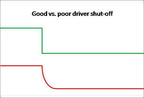
The diagram above is a rough approximation of what a scope trace will look like when the driver of a particular shift solenoid shuts off cleanly as indicated by the green trace, as opposed to when the driver does not shut off cleanly, as indicated by the red trace.
As mentioned elsewhere, current is what determines how well a solenoid functions, so when a shift solenoid’s driver is defective or corrupted, it can happen that a particular hydraulic circuit can remain under pressure for longer than normal, since the shift solenoid will remain energised until the driver circuit shuts off completely-if it shuts off at all. The effect of this is somewhat analogous to when an ignition coil does not discharge completely; the current oscillates in the circuit, and can take much longer than usual to dissipate fully.
However, in the case of transmission shift solenoids, a partially energised driver circuit can maintain hydraulic pressure in a valve body circuit because either the shift solenoid does not return to its “off” state completely, or it takes a longer time than normal to do so. In either case, the effect is usually a delayed shift into the next higher or lower ratio, which may or may not be harsh when it does happen.
Diagnosing this type of issue would generally involve driving the vehicle normally with a scope spliced into the transmission control system. As before, wire colour coding and scope connections can be obtained from service information, but the object in this case is to freeze the scope display at the moment the shift happens. If you get this right, you can use the scope’s time cursors to measure the time delay between the moment the ECU commanded a shift, and when the shift actually occurred.
Ideally, a shift should follow a shift command almost instantly- typically, within a few milliseconds. Thus, if you measure a significant time delay between the shift command and the actual shift into the next ratio, it is almost certain that the affected shift solenoid’s driver is not shutting off cleanly, which will be confirmed by a less than precipitous current drop-off as shown in the red trace above.
So now that you know what is causing the delayed shifts on a particular vehicle, where will you draw the line? Will you refer the vehicle to the dealership or a competitor, or would you keep the job in-house and replace the ECU/TCM yourself?
Note though that before you replace the ECU/TCM, it is always a good idea to check for TSB’s that describe this kind of problem on the affected transmission since in many cases, a simple reprogramming of the ECU with updated software will resolve the issue. Be aware though that even if a relevant TSB recommends reprogramming of an ECU/TCM, this does not always work, so if the issue persists you may have to replace the ECU/TCM.
Limited space precludes the discussion of other types of common automatic transmission issues, but the two examples in this article should illustrate the point that it is possible to diagnose many issues and problems simply by using knowledge you already possess to design creative diagnostic procedures.
We also hope that you will begin to see automatic transmissions and their many issues as a way to generate additional business and income, as opposed to being arcane contraptions that are always best left to dealerships and specialist repairers.
