Have you only ever thought of the intake manifold on an engine merely as a set of pipes that channels intake air into the engine? Well, an intake manifold does do that, and while it usually gets in the way when you want to work on something else, the fact is that an intake manifold on a modern engine is a highly engineered component that is critical to efficient engine operation. In this article, we will briefly discuss the importance of intake manifold design, as well as the various means and strategies engine designers have adopted to increase the efficiency of intake manifolds, starting with this question-
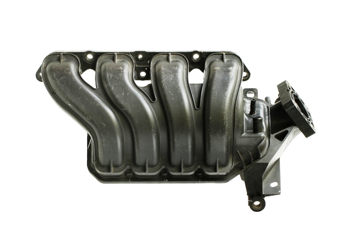
Intake runners are the actual tubes that channel intake air from a reservoir, known as a “plenum” to the intake ports. The image above shows a typical intake manifold, on which the runners connect to the plenum individually, as opposed to branching off from a single exit point as was usual on older manifolds.
While it might appear that the runners on this example are of an unequal length, this is not the case. Note that the runner on the extreme right has a pronounced “kink” in it to bring it to the same length as the runner on the extreme left. In practical terms, runner length is defined as the distance between the manifold’s mating surface with the cylinder head to a point, or line drawn through the plenum that is shared by all the runners. Which brings us to the role runner length plays in manifold design by asking this question-
Even though this article is intended to discuss various active intake runner control strategies, the length of the runners can be thought of as a sort of “passive” runner control strategy. Here is why-
When an engine runs, the intake strokes of the pistons create a negative pressure (partial vacuum) in the manifold plenum, but basic physics demands that the air that is being “sucked” out of the plenum must be replaced by air being pushed into the plenum under atmospheric pressure. Let us look at this process in some more detail-
As, say, piston number one moves downward on its intake stroke while the intake valve is open, the volume of the intake manifold increases by virtue of the fact that cylinder number one is now connected to the manifold through the open intake valve(s). As the piston continues its downward motion, the volume keeps on increasing, and to compensate for the progressive decrease in manifold pressure, atmospheric pressure pushes ambient air into the manifold to restore the balance. However, since the air moving through runner number one can travel at several metres per second, this “slug” of air possesses both considerable mass as the result of its volume, and momentum because of its movement through the runner.
The slug of air will keep on moving until something stops it, which in this case, is the intake valve(s) that suddenly slam(s) shut. When this happens, the moving slug of air bounces off the now-closed intake port, and is reflected back down the runner into the plenum. This phenomenon is known as a “pressure wave”, and this pressure wave will rebound off the opposite face of the plenum and back into the runner at a speed that will cause the bouncing slug of air to reach the intake valve at the exact moment the intake valve(s) open(s) for the piston’s next intake stroke. Provided of course, that the engine designer got both the diameter and length of the intake runners right.
In practice though, this process only works well when the engine is running at a constant speed, since under these conditions, the frequency of the pressure waves match the frequency at which the intake valves open and close reasonably closely. However, continually changing engine speeds continually sets up pressure waves with different frequencies, and while some frequencies might cancel each other out, the result is always that some pressure wave frequencies are superimposed on each other in such a chaotic fashion that airflow through both the plenum and individual runners can be seriously impeded.
While this condition was not of much consequence on the engines of thirty years ago, the introduction of ever more stringent emission-control regulations necessitated the need to improve the combustion processes in modern engines by means of improving the control of fuel trims, which could not be done successfully if airflow to individual cylinders could not be improved. Therefore, engine designers adopted active runner control strategies, the first of which was-
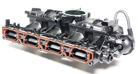
The image above shows the typical appearance and arrangement of a set of runner control flaps; in this example, the flaps are in the open position.
Runner control flaps can be thought of as a set of secondary throttle flaps, whose purpose it is to control the speed at which intake air flows into the intake ports. In practice, the flaps never close off the intake ports completely; in the closed position, the flaps reduce the effective diameter of the intake runner by about 60% at low engine speeds, with “low” being about 3000 RPM on most applications.
Nonetheless, the practical effect of runner control flaps is that since they reduce the diameter of the runner at low engine speeds, the reduced diameter increases the intake air’s flow rate- much like the flow rate of a wide, slow-moving river is increased when it passes through a narrow gorge. The advantages of an increase rate of air flow is firstly that pressure waves are partially damped out, and secondly, that since the air is moving faster, more air is able to pass into the cylinder than would have been possible without the restriction.
As a practical matter, the increased airflow produces increased torque at low engine speeds since combustion is improved, which in turn, makes it easier for the ECU to control both long and short-term fuel trims to reduce emissions.
NOTE: On some applications, most notably Ford and related makes, the intake manifold has two separate, but relatively small-diameter runners for each cylinder. On these applications, the runner control flaps close off one runner completely at low engine speeds to increase the airflow rate through the other runner.
At engine speeds above 3000 RPM, the ECU commands the runner control flaps open and keeps them open until the engine speed again approaches, or falls below 3000 RPM. However, while this control strategy increases power and reduces emissions at low engine speeds, it has some serious drawbacks. Let us look at some disadvantages of runner control flaps-
Limited operating range
Generally, no progressive movement is possible. The flaps are either open, or they are closed, which means that at mid-range engine speeds, the flaps contribute nothing towards improving the engine’s power delivery characteristics, or towards reducing emissions.
No default position
Regardless of whether the runner control flaps are controlled with electronically controlled stepper motors or with a vacuum actuator, the flaps remain in the position they were in when the control system fails. Thus, if the runner control flap control system fails in the closed position, engine performance is seriously affected at high engine speeds because the flaps impede airflow in the closed position.
The system is unreliable
This is especially true on applications that are notorious for their high oil consumption rates. On these applications, the flaps become sticky with carbon deposits that can eventually impede, or even prevent all movement of the flaps. Other common failures include-
Replacement of the flaps is not always possible
While individual flaps can be replaced on some applications, in many cases the only reliable repair option is to replace the entire intake manifold.
While intake runner control flaps were reasonably effective in improving the flow dynamics of air through intake manifolds, the advent of variable length intake manifolds has made it possible to control the flow rate of intake air over a wider range of engine operating conditions.
The image above shows a variable length intake manifold from a Honda application, in which the blue arrows represent the airflow through the manifold at different engine speeds. Note that depending on the engine speed, the length of the flow path of the intake air either increases or decreases, which is analogous to the manner in which an artificial restriction (runner control flaps) increases or decreases the flow rate of the intake air.
Note however, that in this example, the intake air can only follow a short, or a long path- there is no intermediate path to accommodate mid-range engine speeds. To address this problem, some designs incorporate third, intermediate-length path that increases the systems’ operating range, and some Audi V8 engines have been using these three-stage variable length intake manifolds to produce measureable improvements in both power delivery and fuel economy.
Variable length intake manifolds have now largely replaced intake manifold runner control flaps, but as with all automotive technologies, design specifics vary, as do the names manufacturers give to their version of what is essentially the same technology. For instance, BMW calls their version of variable length manifolds DISA (Differentiated Intake System Actuator), while Toyota and Chrysler call their versions T-VIS (Toyota Variable Induction System) and AIM (Active Intake Manifold), respectively.
However, on some designs, and most notably some BMW applications, the simple control valve that switches the intake air path between the long and short runners has been replaced with a “scroll-like” device that can be rotated with a stepper motor to create an almost infinitely variable-length flow path to suit all engine speeds and loads.
The actual design of the “scroll” is too complex to describe here but in essence, the “scroll” forces the intake air to flow around it one or more times before it enters the engine. In practice, the distance that the intake air is forced to travel around the device is roughly equivalent to the air flowing through a runner of the same length, so by altering the position of the “scroll” within the manifold, the distance the intake air has to travel can be varied through an almost infinite range.
Despite their increased efficiency however, variable length intake manifolds are just as prone to failure as runner control flap systems are. Some common failures include-
Broken switching vanes
The flap, or vane that switches the airflow between long and short flow paths has become known as DISA valves, although it should properly only apply to BMW applications. Nonetheless, failure of these valves is a relatively common problem that causes a sound much like a sticky valve lifter when it starts spinning around its pivot point. On many applications, this valve can be replaced by partially disassembling the manifold.
TIP: To ensure proper operation of the replacement DISA valve, ensure that all vacuum and electrical connections are sound, and that all stored fault codes are cleared before the vehicle is returned to service. If driveability issues persist, test the operation of the position switch/sensor.
Position switch failure
Position switch failure is common, and most failures can be attributed to heat exposure over long periods, vibration, and the build-up of carbon on the DISA valve that can inhibit the free movement of the valve. However, in many cases where codes relating to the position switch are set and stored, the real problem is not actually the position switch, but rather the inhibited movement or outright failure of the DISA valve.
Vacuum actuator failure
As with all vacuum actuators, the diaphragm can become brittle, which causes it to fail. Split, cracked, perforated, and/or dislodged vacuum lines can also cause the DISA valve’s control system to fail.
Like all automotive technologies, intake manifolds will continue to evolve to keep pace with developments in other aspects of fuel and engine management systems. In fact, Ferrari has managed to develop a variable intake manifold in which the runners physically change their lengths as parts of the runners telescope in and out of each other. However, how successful this design will prove to be under real-world driving conditions remains to be seen.
