How often does it happen to you that the reprogramming of control modules is aborted by your scan tool(s), or programming updates and/or patches and fixes don't seem to "take", no matter how many times you repeat the reprogramming procedure? If this happens to you a lot, you are not alone; many technicians encounter this issue regularly, and in this article, we will discuss possible reasons why reprogramming events are sometimes unsuccessful and offer useful insights on how to avoid unsuccessful programming events in the future. Let start with this question-
There are many possible reasons why one or more control modules may require reprogramming, and if you are an experienced technician, you likely know them all. However, if you are new to the car repair industry and/or have not had much exposure to module reprogramming, which incidentally, many new mechanics see as a dark art), you should know that many, if not most programming and/or memory failures are the direct result of unstable system voltages, and/or system voltages that are outside of a range specified by the vehicle manufacturer.
While the statement above covers a lot of ground from a diagnostic perspective, the biggest problem with reprogramming procedures has far less to do with the increasing complexity of modern automotive electrical systems, than it has to do with the low fault tolerance of electrical systems as a whole. One expression of low fault intolerance involves checksums, which in their simplest form represent the total, or sum, of all the bytes of information that comprises a data transmission between two or more control modules.
In practice, the sum of all the bytes of information in a data transmission (or data package) is encoded and tacked onto the end of a transmission. The receiving control module then compares the encoded total number of bytes in the transmission, i.e., the checksum, to the actual data component of the transmission to verify that it had received all of the transmitted data from the transmitting control module. If the two values do not match exactly for any reason, the receiving control module will set a communications-related fault code if all the enabling conditions for that particular fault code are met.
At first reading, none of the above may appear to have anything to do with control module programming failures, but the fact is that communication between a transmitting scan tool and a receiving control module on a vehicle works in the same way that communication between two control modules on a vehicle works. Therefore, for a programming procedure to be successful, the communication line between the transmitting scan tool and the receiving control module has to be a), free of any electromagnetic interference, and b), stable enough to allow for the uninterrupted transmission of data.
More importantly, though, the current in all affected circuits during the data transmission or programming event must be within the range specified by the vehicle manufacturer. This is required to prevent the scan tool from aborting the procedure because a buffer overflow error had occurred, and/or to prevent the receiving control module from rejecting the transmission to protect itself against, for instance, voltage spikes, which begs this question-
Well, yes, and no. In some cases, a fully charged battery that supplies a constant 12 volts can supply enough power to complete some programming functions. However, power requirements vary between manufacturers, and there are many procedures on some applications* that have very specific power requirements but generally, currents required for programming typically range from 13.4 volts to 13.7 volts, while others can be as high as 14 volts and above.
* One typical example is the procedure to bleed and calibrate the ABS brake system of some Ford Escape hybrid models. On these vehicles, the procedure can take more than an hour, and it requires that the key remain in the "ON" position for the duration of the procedure. This is usually not a problem if the LSI battery is in perfect condition, but if it is not, its output during the procedure can drop to the point where the scan tool will abort the procedure due to an insufficient system voltage.
Thus, power requirements for reprogramming events must be determined from reliable OEM-level service information, much of which can be obtained here, albeit at the cost of a subscription since this information can often not be obtained from car manufacturers directly. Nonetheless, the power requirements for some reprogramming events are often only published in TSB’s that describe fixes for particular programming issues on affected vehicles, so be sure to also search for relevant service bulletins before you attempt to reprogram any control module. This is particularly important since some service bulletins require that system voltages on the affected vehicle be either stabilized or boosted to the required level by an external power supply before programming can begin.
However, the title of this article references “dirty power”, so what do we mean by that? Let us look at this issue in some detail, starting with saying that-
In the context of control module programming, power supplies are typically battery chargers, and you will no doubt have noticed that the battery chargers in your workshop state their outputs only in Amps. Battery charger specs might state that the unit is a 12-volt charger, but the specs typically state neither output voltage, nor a maximum output voltage, and herein lays the problem, since automotive electrical systems typically do not operate at 12 volts. Electrical systems typically operate with OCV (Open Circuit Voltage) values of between 12.6V and around 14V when the engine is running.
More to the point though, many battery charger manufacturers claim that their products deliver “clean and stable” power, and while this is true in some cases, you will never know what sort of current you are getting from any of the chargers in your workshop unless you check their output currents with an oscilloscope. Below is an example of a “dirty” current-
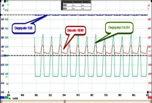
Image source: https://cloreautomotive.com/blog/need-clean-power-vehicle-repairs/
In this example of an actual dirty charging current, the green trace represents the charging current in Amps, but note that it is being delivered in pulses that vary in amplitude from zero to 30 Amps. The smaller red trace represents voltage, but note that this current is also delivered in 180-millivolt pulses. The blue horizontal line near the top of the frame represents the charging voltage, and although it is relatively stable, it hovers around the 16V mark, which is way above the generally accepted 14.2V required by the normal flooded battery that was fitted to this vehicle.
The above is admittedly an extreme example of a dirty current, but the fact is that charging currents like this will almost certainly not allow the successful programming of control modules, all of which are designed to work with “clean” power supplies, an example of which is shown below-
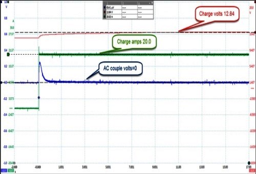
Image source: https://cloreautomotive.com/blog/wp-content/uploads/2015/12/figure-4.jpg
This is an actual example of an almost perfectly "clean" power supply delivered by a microprocessor-controlled battery charger. Note the complete absence of spikes and dips, which is the main characteristic of currents that makes control modules operate efficiently. Programming a control module while such a current is available ensures successful programming events and procedures.
However, there is another form of current contamination to be aware of. This is known as “AC ripple”, a typical example of which is shown below-
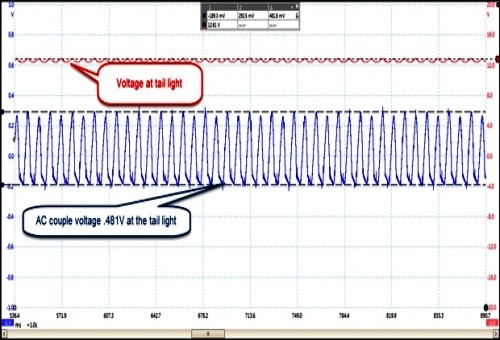
Image source: https://cloreautomotive.com/blog/wp-content/uploads/2015/12/Figure-5.jpg
AC ripple currents are typically caused by defective diodes in rectifiers and can be checked at any electrical consumer that is activated while the engine is running, and in this actual example, the trace was taken from one tail light. Note the red trace near the top of the frame; this shows the frequency of the AC ripple current, while the blue trace shows the amplitude of the AC ripple current that has infected the entire electrical system.
In this example, the AC ripple current measures close to 0.5V, which is strong enough to produce effects such as rough idling or fluctuating idling speeds, loud buzzing sounds from audio systems, overheating of circuits and/or electronic components, and even component or control module failure when the ripple current exceeds maximum allowable thresholds. Of more immediate concern is the fact that since AC ripple currents represent wasted power, an excessive AC ripple current in a DC circuit can reduce the current required for successful programming of a module to the point where either the scan tool or the affected module will abort the programming attempt, or prevent the event from initiating in the first place.
The above are necessarily brief descriptions of complex conditions and/or requirements that come into play when you have to perform programming procedures. However, much of the guesswork in troubleshooting programming failures can be removed by using a stable power supply, but how do you know which battery chargers deliver are stable currents and which do not? This is not always easy to determine unless you scope all the chargers on the market today before buying one, but failing that, we suggest that you-
As with all high-quality tools and equipment, there is always a direct correlation between price and quality, so keep in mind that if you want a fit-for-its-purpose product, you need to be prepared to pay the asking price for it, because you will get what you pay for. From a technical perspective, however, we suggest that you look for the following attributes in a battery charger-
Power delivery
Since programming power requirements vary significantly between vehicle manufacturers, we suggest that you work backwards from the OEM specs of all the vehicles you regularly encounter. For instance, your power supply needs to be able to meet, but ideally, exceed the power requirement(s) of the vehicle(s) that require the most power, which means that you will likely require a charger in the 80 Amp to 100 Amp range.
Controllability
Just as you need to be able to meet the highest power requirements of all the vehicles that you work on, so you need to be able to supply lower levels of current when you need to. For this reason, we suggest you look for a charger that allows you to adjust the output current to match the power requirements of the vehicle you are working on exactly. Note though that while most control modules are designed to work with currents that are above or below the ideal without adverse effects, these current ranges are typically very narrow.
Therefore, if you cannot adjust a power supply to deliver a specified current exactly, you need to be able to supply a current that does not deviate from the specified current value by more than a maximum of 2-3%.
Stability
In this context, "stability" refers to AC ripple in the charger's output current, or more precisely, to the absence of AC ripple currents in the charger's output current. The presence of AC ripple in DC currents is the second biggest reason why programming events fail after insufficient or excessive currents, so make sure the charger you buy has adequate and effective current filtration mechanisms.
Responsiveness
Many programming events are characterised by fluctuations in system voltages as software in both the scan tool and the vehicle activates and deactivates various other control modules and/or systems in response to the programming process. Therefore, the power supply you use has to be able to adapt to changes in system voltages as they occur to reduce possible negative effects of voltage fluctuations on the programming event.
Charging capability
It should be noted that no power supply, no matter how stable it is, can or should replace the vehicles' own fully charged power source (battery) at any point during a programming event. Thus, if the battery is not fully charged, it should be charged with a multi-stage charger that is capable of charging that particular battery type before programming begins. For instance, since AGM batteries have different charging profiles than say, conventional flooded batteries, the charger in question should have the ability to charge the battery that is recommended for the vehicle in question.
Therefore, the charger you buy should be able to charge all modern battery types and constructions. Ideally, though, the charger should also have the ability to a), detect the battery type/construction automatically, and b), to perform diagnostic functions on charging systems as well as on all types of car batteries. We realize that this type of battery charger is the most expensive, but using such a charger during programming events virtually eliminates the possibility of programming events being unsuccessful, which leaves us with this-
Far from being an arcane and dark art, control module programming is a relatively straightforward procedure that should be well within the capabilities of all reasonably competent mechanics and technicians. Of course, how well or otherwise the procedure works depends on how closely service information is followed concerning the power/current required for the procedure, as well as on the capabilities of the scan tool and the integrity of the software used.
If all the required conditions are met, an actual programming event involves little more than following prompts- either on the scan tool screen or in service information, and this being the case, we hope that this article has inspired you to undertake more control module programming jobs.
