
If the truth were told, few of us have more than a very basic grasp of electrical theory, except, of course, for the specialist electrical diagnosticians among us. In fact, it would be reasonable to say that most of us hated studying electrical theory in trade school, and the proof of that lies in the fact that one would be hard-pressed to find a technician that can recite even one of say, Faraday's laws, or Ohm's most famous law, or Lenzs’ laws of magnetism.
There are many other examples of laws of electricity we have forgotten about or never bothered to learn, but the fact of the matter is that when we do not know or understand at least the most fundamental electrical laws and principles, electrical diagnostics becomes much more difficult than it needs to be. Unfortunately, we cannot deal with all the electrical laws and principles that make modern cars work in one article, but we can do the next best thing, which is to focus on one law formulated by Emil Lenz in 1834, which law governs (among many other things) the relationship between current flow and magnetism. Before we get to the specifics of how this law applies to modern electrical diagnostics, let us look at-
To give it its full name, Lenz’s Law of Electromagnetic Induction states that “…the direction of the current induced in a conductor by a changing magnetic field (as per Faraday’s law of electromagnetic induction) is such that the magnetic field created by the induced current opposes the initial changing magnetic field which produced it.” Source: https://www.electrical4u.com/lenz-law-of-electromagnetic-induction/
In translation, this means that when a current flows through a conductor, the magnetic field that the current flow creates, creates its own magnetic field, and this (second) magnetic field’s direction will always oppose the direction of the magnetic field that created it [the first magnetic field].
This phenomenon can be proven in different ways; the theory can be proven mathematically, while the practice can be demonstrated with magnets and coils of copper wire, but for us as technicians, one proof lies in the so-called “pintle bumps” we see in some oscilloscope waveforms. We will return to “pintle bumps” later on in this article, but for our purposes, we can define Lenz’s law as follows, but note that the definition below is a gross oversimplification of a group of exceedingly complex scientific laws and principles-
“Electrical currents always induce magnetic fields around conductors and a) the strength of the induced magnetic fields will always have an effect on the current flow and b) the strength of such induced magnetic fields will always be proportional to the intensity of the currents that created them.”
So, while Emil Lenz did not discover magnetism he did formulate a law that states that-
We need not delve into the mathematic proofs of these concepts here, but we can observe the effects of these concepts directly every time we use an amp clamp or amp probe. Consider the image below-
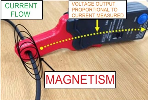
Image source: https://www.vehicleservicepros.com/service-repair/battery-and-electrical/article/21293485/lenzs-law-the-anatomy-of-the-current-waveform
Contrary to popular belief, the value we see expressed or displayed on amp clamps and probes is not a direct measurement of the current (Amps) flowing through a conductor in a circuit. As shown here, the amp clamp measures the strength of the magnetic field around the conductor and then calculates both the current and voltage flowing through the circuit at that point, using advanced algorithms that are derived from Lenz’s law.
Why is this important, you may ask? You may well ask because the relationship between currents and magnetism forms the basis of the operating principles of all electrical consumers on all vehicles. Put differently, this means that no matter what any manufacturer calls any given component; all electrically operated solenoids, electrical motors, A/C compressor clutches, and the like all work in exactly the same way, and largely fail for the same reasons.
For example, all fuel injectors that work with coils of copper wire use Lenz’s law to work, as do all starter solenoids, shift solenoids in transmissions, oil flow control valves in VVT/VCT systems, and pressure control solenoids in torque converter lock-up clutches. Other examples include ignition coils, internal blower and radiator fan motors, starter motors, electronic throttle control stepper motors, and many EGR valves.
At the risk of putting too fine a point on this, the fact is that although all of the above components use different currents and voltages to work, the operation of all of the above components is also influenced and/or affected by the magnetic fields that arise from the currents that drive them. Therefore, we can use the same approach to diagnose issues with these components, which, if one keeps one’s wits about one’s self, removes much of the guesswork that is inherent in electrical diagnostics from the proverbial equation.
Not convinced? Then consider this: would you rather spend three hours removing a suspect starter motor from some vehicles to test the motor on a test bench, or would you rather spend ten minutes hooking up an oscilloscope to obtain a visual representation of how the starter motor reacts to a current? Most of us would no doubt choose the latter option, and in the following section of this article, we will discuss-
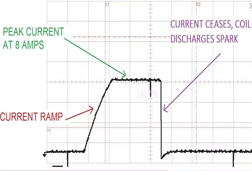
Image source:https://www.vehicleservicepros.com/service-repair/battery-and-electrical/article/21293485/lenzs-law-the-anatomy-of-the-current-waveform
This image shows a zoomed-out known-good ignition coil waveform, but which part or aspect of this waveform is a) the most critical from a diagnostic perspective, and b) proves that this particular ignition coil is working as expected? Would you say it is the measured peak amps, or the part labelled “current ramp”?
This might sound like a trick question because the peak current is important the fact is that the current ramp is more important from both an operational and diagnostic perspective. Recall that we said all currents create magnetic fields, and that such induced magnetic fields are oriented in a direction that opposes the direction of the currents that created them.
Well, in this example, the angle of the ramp represents the drag that the magnetic field exerts on the current flowing into the ignition coil's primary windings. The elapsed time between the bottom and top of the ramp is commonly known as the coil's ramp-up time, or more properly, its dwell time, but regardless of what we call it, the angle of the ramp demonstrates the effect of the induced magnetic field on the coil's windings.
Moreover, the angle of this ramp also shows that the magnetic field in the primary windings will be intense enough to “jump” into the secondary windings to create the ignition spark when the magnetic field in the secondary windings collapses as a result of a driver circuit removing power from the coil’s primary windings.
This action demonstrates another part of Lenz’s law; magnetic fields induce currents in conductors, which in the case of a spark plug, is the pointy end of the spark plug’s central electrode.
Let us look at another example of Lenz’s law in action, but this time, in an ignition coil with shorted windings. Consider the image below-
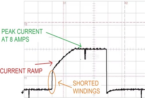
Image source:https://www.vehicleservicepros.com/service-repair/battery-and-electrical/article/21293485/lenzs-law-the-anatomy-of-the-current-waveform
In this example, the peak current is roughly the same as in the known good trace, but the most noteworthy aspect of this known bad trace is the short vertical line in the current ramp, shown here circled in red.
In all cases, current ramps are displayed over time and in the case of ignition coil ramps, the time it takes for a coil current ramp is usually only a few milliseconds. Thus, since there is always a time factor involved in current ramps, the short vertical line shows that the inrush current's path is bypassing several (or many) of the coil's windings.
However, since there are no faults in the primary circuit outside of the coil, the current will continue to build until it overcomes the interrupted pathway, as shown here when the current ramp begins to build after the vertical step. However, the problem here is this; an increase in current caused by the short circuit in the windings should yield an increased magnetic field, but it does not. Here is why-
Since the short circuit effectively reduced the number of primary windings, the magnetic field the current creates will correlate to the number of energised windings, and since there are now fewer energised windings, the magnetic field in the primary windings will necessarily be weaker than in a fully functional coil. Moreover, when power is removed from the coil and the residual magnetic field collapses into the secondary windings, the secondary windings might not be able to create a sufficiently strong current to generate an ignition spark, and the engine will misfire as a result.
So while the correlation between the input current and the magnetic field it creates remains valid, the reduced number of windings produced a reduced magnetic field that may or may not be able to produce an ignition spark.
As a practical matter, however, the diagnostic information that waveforms like the above examples contain can only be decoded if we can a) recognise the features of such waveforms, and b) learn to recognise anomalous features, such as the vertical step in a current ramp, for what they are.
This writer is aware of the fact that interpreting anomalous features of current ramps is difficult if one does not have at least a working knowledge of the scientific laws and principles that underpin the structure, or anatomy of the various types of waveforms we see displayed on our oscilloscopes almost every day.
Of course, as with almost anything else in electrical diagnostics, learning to interpret waveforms correctly is a rather steep learning curve that takes dedication and lots of practice to climb successfully, but the advantages of being able to test components remotely are well worth the time and effort. To illustrate this point, let us consider one more example of Lenz's law in action by looking at-
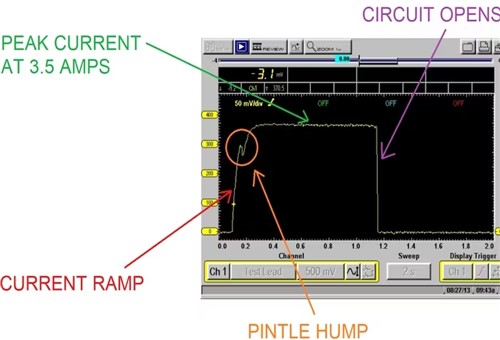
Image source:https://www.vehicleservicepros.com/service-repair/battery-and-electrical/article/21293485/lenzs-law-the-anatomy-of-the-current-waveform
We stated elsewhere that all electrically operated solenoids and other components that use magnetism to perform work (or a particular function) work on the same basic principles, regardless of what different manufacturers call these components in their technical literature and service/repair information. One example of this will suffice: Toyota uses the word “igniter” for ignition coils, while all other manufacturers call ignition coils, well- “ignition coils”.
Nonetheless, let us consider the image above, which is a known good scope trace of the operation of an A/C compressor clutch. Note that like the ignition coil trace, this trace also shows a current ramp but because a compressor clutch has fewer windings than an ignition coil, the windings reach saturation point sooner, which also means that the magnetic field reaches its maximum intensity sooner. This explains the steep angle of the current ramp, which is a direct function of the clutch coil’s dwell, or ramp-up time.
The most pertinent aspect of this current ramp is not its steep angle, but the small “bump” (circled in red) that occurs near the top of the current ramp. This bump is characteristic of the current ramps of solenoids; while these bumps do not always appear at the same point in current ramps, the fact that the bump occurs is evidence that the solenoid or coil had cycled.
In all cases, the movement of the solenoid shuttle or pintle, or in this case the compressor clutch’s engagement, temporarily decreases the current flow through the coil, thereby creating a small dip in the overall current ramp.
Thus, from a diagnostic perspective, the presence of such a bump in the current ramp tells us two things. The first is that the solenoids’ (or clutch in this case) control circuit is intact, and the second thing is that the clutch had engaged or the solenoid’s shuttle had been pulled off its seat. In fact, some control modules actively look for this bump in the current ramp as a means to determine the ON/OFF status of the solenoid or clutch.
Now consider the image below-
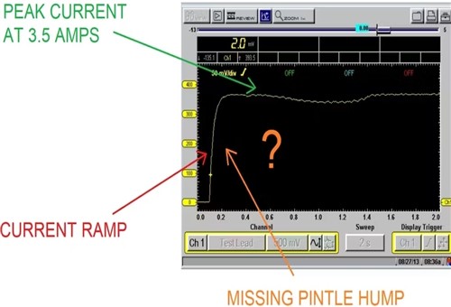
Image source:https://www.vehicleservicepros.com/service-repair/battery-and-electrical/article/21293485/lenzs-law-the-anatomy-of-the-current-waveform
This scope trace is the actual trace that was obtained during a process to diagnose a non-functional A/C compressor clutch. Note that while the peak current is a) roughly the same as in the previous example, and b) the current ramp has roughly the same angle and duration, there is no pintle bump in the current ramp.
This also tells us two things. The first is that the clutch’s control circuit is intact because if it were not, we would not see a current ramp as a result of the coil being energised. The second thing is that the absence of a pintle bump in the current ramp proves that the clutch did not engage. Therefore, if we know how an A/C compressor’s clutch works, the only valid inference we can make is that the induced magnetic field could not overcome the excessively large air gap in the clutch. This inference is based on the facts that-
Although this was an exceedingly easy diagnosis to make, it was made easier still by the fact that a targeted test could be performed remotely in less than five minutes. The alternative would have been to either rig up jumper wires to test the clutch with direct battery power, or to spend an hour or more removing splash guards and other things to gain access to the compressor- just to measure the air gap in the clutch.
Moreover, this easy diagnosis would have been accurate on any vehicle whose A/C system uses a magnetic clutch, regardless of which manufacturer made the vehicle or the A/C system, simply because Lenz’s law works equally well on all vehicle makes and models, which leaves us with this-
Electrical diagnostics is not getting any easier despite the vast arsenal of modern test equipment that is available to all mechanics and technicians today. However, the problem with having access to any number of diagnostic tools is that it can be easy to lose sight not only of what it is we are testing but also of why we are testing it.
Not knowing why we are testing a certain part or component is a sure way to fall into diagnostic rabbit holes, but once one realises that all cars are essentially the same and that they all work in much the same way, following some simple laws to diagnose similar faults on all cars makes electrical diagnostics a whole lot easier.
You may not have heard of Emil Lenz before, but now that you have seen his simplest law in action, would you ever consider diagnosing electrical issues on say, Ford vehicles differently than you would diagnose electrical issues on say, Toyota vehicles? Of course, you wouldn’t- seeing that the laws of electricity are the same everywhere in the automotive world.