Although finding and fixing parasitic battery drains usually falls within the purview of auto electricians, there may come a time when you, as a non-electrician may be called upon to diagnose and fix a parasitic battery drain. However, parasitic battery drains come in two flavours; one that can run a battery down in a matter of hours, and another that can sometimes take a week or longer to drain a battery to the point where it cannot start a vehicle. While the first kind of battery drain is usually relatively easy to locate and repair, the second kind is often described as "phantom drains", and finding them requires some finesse. Thus, in this article, we will discuss a logical approach to phantom battery drains that should enable even non-electricians to diagnose and fix these kinds of issues, starting with saying that-
This statement might seem counter-intuitive at first glance, but the fact is that even when a vehicle is switched off and in a state of "sleep", several control modules remain awake and will continue to draw power for as long as power is available. Exactly which modules remain awake depends on the vehicle, but these typically include the KAM (Keep Alive Memory), a variety of telematics-related modules (if fitted), DTC storage, clocks, the factory-fitted alarm/security/anti-theft system, or in some cases, aftermarket tracking devices.
However, the number of control modules on modern vehicles has been increasing steadily in recent years, and given that the normal parasitic current drain is about 1-3 mA per module, it is not uncommon to see a total parasitic current drain of up to 50 mA on some vehicles, and that is after the vehicle had gone to sleep. Therefore, to counter excessive parasitic drains on sleeping vehicles, many manufacturers have been making greater use of both EEPROM functionalities to increase permanent memory storage, and improved power management strategies/algorithms to decrease parasitic power drains to an unofficial average of about 5 – 10 mA even on high-end vehicles that bristle with control modules.
Nonetheless, new vehicles are not entirely immune to "old-school" parasitic drains such as defective door latches, stuck-closed glove box/dome/courtesy light switches, leaking diodes in alternators, and even dirt on batteries that provide some conductivity between the poles. While these types of issues are almost always easy to resolve, phantom or seemingly inexplicable parasitic drains, and especially intermittent battery drains are another matter entirely. Nevertheless, since taking a logical approach to the problem is always helpful, the steps (in order of importance) outlined below should enable you to formulate an appropriate diagnostic strategy even if you are not an auto electrician. Let us start at the beginning, which is to-
Parasitic power drains can set many trouble codes and in many cases, most stored codes will have set as a result of the power drain, as opposed to them having caused the power drain. Therefore, before you do anything else, retrieve and record/document all fault codes from all control modules before clearing any codes. The most useful codes (in a diagnostic sense) are UXXXX codes since U-codes indicate communication issues between control modules. Thus, if you clear codes, including U-codes, you may be erasing valuable diagnostic clues that may not return immediately after powering up either the vehicle or some control modules during your tests.
This might seem obvious, but many "parasitic current draws" are actually defective batteries, poorly performing alternators, slipping drive belts, poor ground connections between the engine and body, failure to reset the power control module/charging system after a battery replacement, and even excessively corroded battery terminals that prevent the efficient operation of the charging system.
It is very easy to confuse any or all of the above with a parasitic power drain, so at a minimum, the battery and charging system must be tested to industry standards at both rest, and when the electrical system is fully loaded to verify that all system components are performing within specifications. Replace the battery and/or any other charging system components that do not perform to specifications.
Note that since hybrid and purely electric vehicles use DC-DC converters that function as alternators, the same at-rest, and loaded charging system tests that apply to conventional vehicles must be performed on hybrid and/or electric vehicles. Be aware, however, that charging system tests on hybrid and electric vehicles are often vehicle specific and rather complex, so be sure to consult reliable service information before testing anything on these vehicles, or drawing conclusions based on test results.
If a problem shows up in the charging system the cure is often relatively easy to implement, but if the charging system is functioning properly and within specifications, you need to start digging deeper, and it is here where you need to take a step back to-
Many new or high-end vehicles never truly go to sleep, so what you need to know is which control modules and their associated circuits remain alive as a function of their normal operation. This is not always easy to determine, but a good starting point would be to consult a manual to familiarise yourself with all the proverbial bells and whistles on the vehicle.
For instance, the vehicle may be performing final checks on the air suspension’s ride height, cycle the A/C system a few times to dry out the ducting, perform EVAP leak tests, or do any number of other things during the hour or so it takes for the vehicle to go to sleep. Vehicles that are equipped with telematics systems may ping or call service centres at regular intervals, or a navigation system may perform automatic updates. While the above actions are perfectly normal, the problem is that it is not always easy to distinguish between regular and intermittent power spikes if you don't know what normal activity you can expect to see on a given vehicle.
One way to separate normal activity from an abnormal activity is to connect* a digital storage oscilloscope to the battery to monitor all electrical activity both during the time it takes for the vehicle to enter sleep mode and after the vehicle had gone to sleep. Note though that you do not necessarily want to know which systems are drawing power at this point; what you want to know is whether or not there are current draws that occur at irregular intervals, or if normal actions draw more power than is specified for any given system(s).
For instance, telematics systems such as OnStar, Lexus Link, etc, typically ping remote servers at regular and very precise intervals that can be as long as 10 minutes, while security systems typically draw small amounts of power at one or two-second intervals as the warning light flashes.
* If you need to leave the bonnet open to connect the oscilloscope, install jumper wires around the bonnet switch to simulate a bonnet-closed condition. Failure to do this could result in several control modules never going into sleep mode, which could greatly affect your test results. Also, remember to remove the key from the ignition, and not to approach the vehicle with the key in your pocket because the keys’ proximity to the vehicle could wake up several control modules.
As the vehicle goes to sleep, your scope trace will show spikes as various control modules perform final checks. Thus, after the vehicle had gone to sleep, the only spikes in the trace should correspond to regular events like for instance, the telematics system pinging remote servers, the security system powering the flashing warning light, or the EVAP system performing leak tests. As a practical matter, the scope trace should be largely flat (except for regular and predictable current draws), after the vehicle had gone to sleep. Therefore, any irregular spikes are indicative of an intermittent parasitic current draw, while a flat trace that measures a higher value than the battery's capacity (typically, 12V) is indicative of a permanent parasitic current draw.
After you have collected data for a few hours, you can simply compare regular current draw spikes with reliable service information before drawing any conclusions based on your data. For instance, if the telematics system draws more than a specified (current) value, you know that the problem is either in the telematics system or in an associated system. However, this is only one half of the problem- the other half involves finding and isolating the actual circuit that is active when it should not be, so let us look at the quickest way to accomplish this, which is by-
Before we get into the specifics of testing circuits, we should mention the fact that some car manufacturers prescribe specific procedures that have to be followed when you are trying to diagnose a parasitic current draw. Some of these procedures could include-
There are other examples of prescribed steps/procedures, and these should be obtained from reliable service information and followed religiously to ensure reliable test results. However, a quick online search will turn up a multitude of posts that describe generic test procedures for parasitic current draws, and many, if not most authors of these tests will tell you to disconnect the battery for one reason or another.
The fact is however that disconnecting the battery when service information does not call for it can have unpredictable results, the most serious of which is erasing and/or the corruption of critical programming in any number of control modules. Another effect is that when you reconnect the battery, you wake up all or most of the control modules in the vehicle, which means that you now have to wait an hour or more for the vehicle to go to sleep again, provided of course, that no control modules had suffered damage. Thus, to avoid potential damage to control modules DO NOT disconnect the battery unless you have reliable service information that specifically says you must disconnect the battery.
So before you begin testing circuits, prepare the vehicle by opening all the doors and tripping the latches into the closed position. Open the bonnet and boot/rear hatch, and install jumper wires around switches to simulate closed conditions. Check that all the windows are closed and that all dome and/or courtesy lights are off before switching off the ignition, removing the key, and placing it as far away from the vehicle as you can. Now you have to wait an hour or so for the vehicle to go to sleep, which time you can use to consider some electrical theory, and more specifically, the theory of voltage drops; the quickest and easiest way to test circuits for parasitic current draws- which begs this question-

Image source: https://www.garagejournal.com/forum/showthread.php?t=375197
The image above shows a perfect example of a severe voltage drop. In this thermal image, a fuse glows bright red as the result of the excessive heat generated by high electrical resistance to current flow, which is the basis of voltage drop measurements.
The easiest way to explain how voltage drop measurements work is to quote Ohm’s Law, which states that voltage equals current multiplied by resistance (V = I * R). Stated differently, one can also say that current equals voltage divided by resistance, which is expressed as (I = V / R). If we apply this law to automotive diagnostics, the voltage is typically a constant 12 volts, while the electrical consumer has an integral resistance to current flowing through it, and it is the combination of these two factors that determine the strength or intensity of a current that flows through a circuit. Note that for our purposes, the resistance of wiring is ignored because this value is typically negligible.
As current flows through a circuit, even the negligible resistance of a conductor (wire) causes minute changes in the intensity of the current from one point in the circuit to any other point. Therefore, if one places the negative probe of a multimeter on a live wire, and the positive probe on the same wire, but further along the wire, it is possible to measure the reduction in the intensity of the current between the probes, which is why-
You may have heard that pulling fuses one by one will eventually reveal a circuit that is active when it should not be. While this is true, the problem with pulling fuses on a modern vehicle is that this method only works when you strike it lucky and pull the fuse on the defective circuit first. Moreover, pulling fuses randomly tends to wake up control modules, which means that you may have to wait for an hour or more for the whole vehicle to go to sleep again after each time you pull a fuse. This is not clearly practical, so here is how to test circuits without removing fuses-
Before you start testing though, bear in mind that at this point you are not trying to determine the strength or intensity* of the parasitic current draw. What you are attempting to do is to identify the circuit in which a parasitic current draw is present, so have a pen and paper ready to note down your test values and the numbers/labels of fuses that are live when they should not be.
* Note that the most reliable test results are obtained by using a good quality digital multimeter set to the millivolt scale, and test probes that have thin, but very sharp points because normal blunt probes are often too big to make proper contact with fuse filaments, hence the need to have thin, sharp-pointed probes.
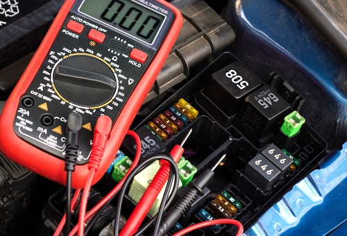
So when you are ready to begin testing, locate all the fuse boxes in the vehicle. Start testing fuses by placing one probe on one end of a fuse's filament, and the other probe on the other end of the fuse filament, as shown below, but remember that since the vehicle is asleep and all electrical consumers are therefore inactive, you will not (or should not) obtain a reading of 12V on any fuse.
If the probes on your test leads are sharp and you have good contact between the fuse and the probes, and if there is current on the fuse, this current will typically fall into the millivolt range. If however, you get a rapidly fluctuating reading, you almost certainly do not have good contacts: reposition the probes and wait for the reading to stabilize. If on the other hand, you do not get a reading at all, that circuit is almost certainly good.
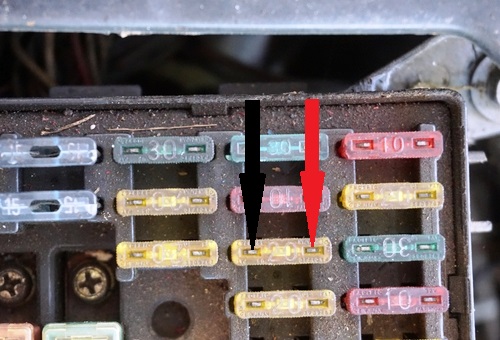
Continue testing all the fuses, fusible links, and relays in this manner, but remember to note down both the reading you get and the number(s) of the fuses, fusible links, and relays you encounter that have current flowing through them. Once you have tested all the fuses, fusible links, and relays it is a simple matter to match the affected fuses with their circuits by consulting a suitable wiring diagram, but if you want to convert your millivolt readings to milliamps, you can download ready-made conversion charts here; an example (partial screenshot) of such a chart that applies to maxi fuses is shown below-
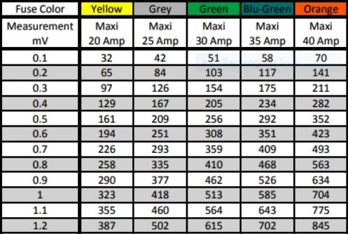
The biggest advantage of using charts like these is that you can easily convert millivolt readings that do not tell you anything, to milliamp readings that are extremely useful for diagnostic purposes because they relate directly to the battery's discharge rate. For instance, if you find a 1.2 millivolt reading on a 40 Amp maxi fuse that should have not have any current flowing through it, you have a battery that is discharging at a rate of 845 milliamp every hour, which is enough to drain a fully charged battery in fairly short order.
Of course, knowing the battery's discharge rate due to a parasitic current draw and fixing the problem are two entirely different things if you are not an auto electrician, but there are some upsides, nevertheless. For instance, you will have definitive proof that a parasitic current drain does indeed exist on the vehicle, which will go a long way towards resolving your customer’s concerns about the “poor quality” of the batteries and alternators he keeps on buying, which leaves us with this-
It should be borne in mind that this article does not pretend to be the last word written on finding parasitic current draws on modern vehicles since there are more complex ways of doing this than performing simple voltage drop tests across fuses to test circuits for parasitic current draws.
However, there is no denying the fact that the voltage drop method is the simplest, easiest, quickest, and most reliable way for non-electricians to find parasitic current draws even on high-end vehicles. The most difficult part of the voltage drop method is often related to preparing the vehicle properly, but understanding the need for the vehicle to be truly asleep before starting voltage drop tests is half the battle won. Therefore, and since the other half is easy to do, no reasonably competent mechanic should ever experience undue difficulties in performing simple voltage drop tests to find a parasitic current draw on (almost) any vehicle.