Although GDI (aka Petrol Direct Injection in markets outside of the US) have been in relatively widespread use since about 2006, only roughly 50% of new vehicles are fitted with these systems, which means that it is very likely that you have not encountered such a system before. While the basic operating principles of port injection and direct injection systems are largely similar, the specifics of direct petrol injection have more in common with diesel common rail injection than with the port petrol injection systems we are all familiar with. Because of this, direct petrol injection systems have different failure modes than port injection systems, so in this article, we will take a closer look at direct petrol injection systems in terms of how they work, and how they fail, starting with this question-
Unlike port injection systems that inject fuel into inlet ports behind the inlet valve(s) at relatively low pressures, direct injection systems inject fuel directly into combustion chambers at pressures that typically vary between about 4.1 bar at low engine speeds/loads and about 200 bar under WOT conditions. While these pressures do not compare to common rail diesel injection pressures, they are nonetheless several orders of magnitude higher than even the most advanced (petrol) port injection systems can deliver.
As a practical matter, all direct petrol injection systems use single-piston mechanical pumps that are driven off a camshaft lobe, much like how many high-pressure injection pumps on common rail diesel engines are driven. Also, like diesel injection systems, direct petrol injection systems use electrically operated lift pumps in the fuel tank to supply the high-pressure pump with fuel. In some cases, the low-pressure supply system uses a return line to return unused fuel to the tank, but more commonly, the lift pump is controlled by a pulse width modulated signal both to control the amount of fuel delivered to the high-pressure pump and to reduce fuel agitation in the tank as a means to reduce evaporative emissions.
Also, high-pressure petrol pumps incorporate a fuel flow control valve and a fuel pressure regulator, both of which are controlled and monitored by an ECU to control and manage the fuel pressure in the high-pressure side of the system. It is perhaps worth noting that ECU’s that are compatible with direct injection systems are vastly more complex than non-compatible ECU’s. For instance, a direct petrol injection system on a four-cylinder engine requires an ECU that can perform up to 40% more calculations per second than a standard ECU, and that can take around 12 million more measurements into account (as compared to a standard ECU) when adapting fuel delivery strategies to suit changes in engine operating conditions.
We need not delve into the complexities of the required control algorithms here, but suffice it to say that to make it possible for direct injection systems to work, these systems also require special injectors that can perform injections in under two milliseconds- even in some injection modes that consist of multiple injection events. To do this, direct injection injectors have very low resistances and are driven by dedicated injector driver circuits that typically use in-line capacitors to increase the 12-volt supply voltage to between 50 and 90 volts to hold the injectors open against the high fuel pressure. The waveform below illustrates the effect of this low resistance on injector operation-
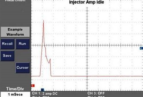
Image source: https://www.autonerdz.com/yabbfiles/Attachments/GDI_Operation.pdf
Note that although direct petrol injection injectors typically work on currents of around 10 Amp, the steep current ramp-up is a direct result of the injectors’ low resistance, while the steep current drop-off under idling is the result of the ECU’s ability to shut off the driver circuit efficiently and cleanly. However, under WOT conditions we see something very interesting, as shown in the example below-
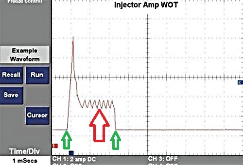
Image source: https://www.autonerdz.com/yabbfiles/Attachments/GDI_Operation.pdf
The most notable aspect of this example waveform is the series of almost-equally spaced “blips” indicated by the red arrow. At first sight, these might appear as a defect in the ECU that prevents the driver circuit from shutting off cleanly, but these blips are normal and they indicate small surges in current as the injector works to keep the pintle open during the injection event.
Note though that these blips do not represent separate injection events; this is a single injection event that starts as the current begins to ramp up, and ends with the large current drop-off as indicated by the green arrows. Note that while the time duration of this injection event is not apparent in this image, single injection events under WOT conditions typically complete in about 1.25 milliseconds or less, which brings us to-
Unlike some port injection systems that can produce multiple injection events during low engine speed conditions, injection events in direct injection systems are for the most part limited to two, and then only under strictly defined conditions. Let us look at how this works in practice, but note that while the injection strategies outlined below apply to Bosch direct injection systems, other systems may employ slightly different specifics or modes of operation-
Homogenous mode
In this mode, which is typically employed during high engine speed/load conditions, a single injection is delivered during the intake stroke, and the combination of the injection volume/timing and piston design typically produces astoichiometric air/fuel mixture. Note that on Bosch systems, a charge motion valve, which is analogous to an intake manifold runner flap, is fully open to allow for normal airflow through the intake manifold during this mode. Note that other designs may employ forced induction to improve airflow through the intake manifold.
Stratified mode
The stratified mode is typically used during low engine speed/load conditions to both reduce emissions and to increase fuel economy. In practice, a single injection event is delivered just before combustion while the charge motion valve is closed to increase the rate of airflow through the intake manifold, which has the effect of improving the mixing of the fuel and air around the sparkplug electrode. The greatest advantage of the stratified mode is that the air/fuel mixture never approaches the cylinder walls to within a distance that will allow the mixture to condense.
Homogenous lean mode
In this mode, the charge motion valve is closed, and the throttle plate is controlled to match some low engine speed/load conditions. One leaner-than-usual injection is delivered during the intake stroke to mix with the turbulent air produced by the closed charge motion valve.
Homogenous stratified mode
This mode is rather complex since it is used mainly as a transition from one mode to another. In practice, the charge motion valve closes at about the same rate that the throttle plate opens, and two injections are delivered. The first injection is very lean, and mixes with the turbulent air during the intake stroke, while the second injection is rich, and delivered just before combustion begins.
Note though that the purpose of the rich injection is to ignite the lean injection, and while it might appear to be counterintuitive, the two injection events consume less fuel than the homogenous mode and produce fewer emissions than the stratified mode.
Homogenous knock protection mode
This mode also delivers two injections; the first during the intake stroke, and the second just before combustion occurs. However, the main difference between the second injection in this mode and the second injection in other modes is that in knock protection mode, the volume and timing of the second injection can be altered to adjust the Lambda value of the total air/fuel mixture. In practice, and since this reduces the formation of NOx without the need to alter either the ignition and/or valve timing, this mode is most commonly used during high engine load conditions.
Stratified catalyst heating mode
This mode also delivers two injections; the first in stratified mode, and the second after combustion had started as a means to increase the exhaust gas temperature to aid in heating the catalytic converter. In practice, some of the fuel injected during the second injection combusts in the exhaust manifold, which greatly reduces the time the catalytic converter(s) require to enter closed-loop operation.
The above is a necessarily brief description of the basic operating principles of direct petrol injection systems, but from our perspective as technicians, the more important question is this-
It turns out that quite a lot can go wrong but since limited space precludes a comprehensive discussion of all possible failure modes on all systems, we can do the next best thing, which is to provide an overview of the most common pattern failures that occur in direct injection systems, starting with-
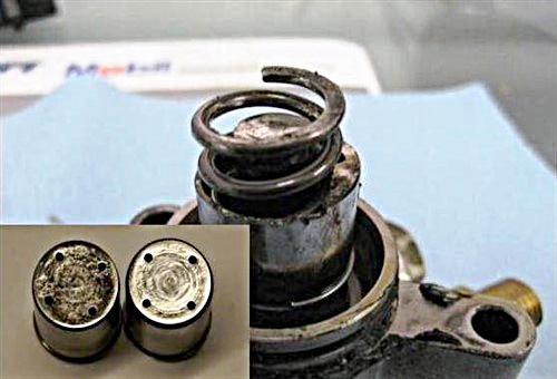
Image source: https://www.autonerdz.com/yabbfiles/Attachments/GDI_Operation.pdf
The main image shows a common type of mechanical pump failure, while the smaller inset shows a severely worn cam follower on the left, with a new, unused cam follower to its right. In this case, the cam follower (not shown here) had worn through completely, which caused the spring to separate from the pump assembly.
This is a common failure mode on some common rail diesel engines, and diesel techs see this all the time but for petrol techs, or petrol techs that don’t do many diesel repairs, this is an unusual sight. Nonetheless, this type of failure has several principal causes, including the following-
Poor oil quality
While oil quality is critically important to keep the camshaft lobes that drive high-pressure fuel pumps properly lubricated, it is equally important to pay proper attention to oil specifications when doing oil changes on vehicles with direct petrol injection systems. For instance, while the manufacturer may prescribe a synthetic oil formulation, SAE-approved synthetic formulations are not necessarily the same as synthetic formulations that are ACEA*-approved.
* Association des Constructeurs Europens d' Automobiles (European Automobile Manufacturers Association)
In the case of ACEA-approved oils, OEM manufacturers can specify or demand that the final formulation conforms to their specific requirements, which is not the case with oil formulations that are approved by the SAE and other regulating bodies. Thus, using the wrong oil is the quickest and easiest way to destroy not only a high-pressure fuel pump but also the camshaft that drives it.
Oil dilution
Not all high-pressure fuel pumps fail catastrophically, but a large percentage of pumps suffer various kinds of failures that cause them to leak fuel into the engine. The most common symptom of this is a rise in oil level, but more importantly, the rise in the oil level means that the oil is dangerously diluted with fuel, which has some severe consequences, including one or both of the following-
The above covers the basics of the most common mechanical failures, but other types of failures and/or issues that are worth mentioning include the following-
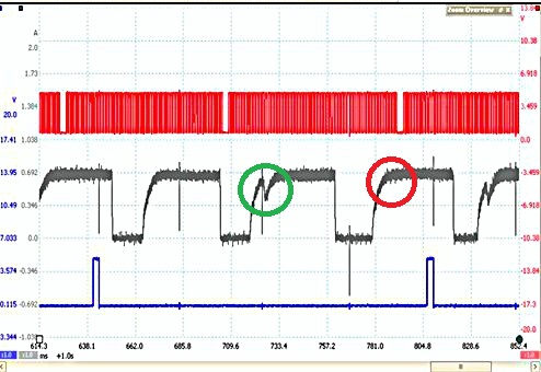
Image source: https://www.searchautoparts.com/sites/default/files/images/ma0420-drive%205A.png
This image shows an example waveform taken from the actuator on a known bad high-pressure fuel pump. In this example, the top, red trace represents ignition events, while the trace below it shows the cyclical current ramps of the pump, but note the red and green circles. In this example, the green circle indicates a normal current "blip" as the pump's pintle is opened, while the red circle indicates a lack of current variation. In translation, this means that there is an intermittent interruption in the supply of pressurised fuel to the fuel rail, which can manifest in the form of multiple stored trouble codes, severe misfires, a no-start, or hard starting condition, or, in some cases, the enforcement of a limp mode.
Note though that this type of failure is distinctly different from variations in fuel pressure that result from crankshaft/camshaft phasing or correlation issues. In these cases, the current variation “blips” will be present (green circles), but they will typically not coincide with ignition and/or compression signals if phasing or correlation issues are present.
As a practical matter though, it can sometimes be extremely difficult to distinguish between the causes and effects of abnormal fuel pressures, and fuel pressures that are within the normal ranges, but that is delivered at the wrong time due to crank/camshaft correlation and/or phasing issues. Therefore, to keep things simple, we have included a few of the most common generic direct petrol injection codes and their definitions here, which should make it a lot easier to distinguish between the most common failure modes-
|
Trouble Code |
Definition |
Notes |
|
P0087 |
Fuel Rail/System Pressure Too Low |
Actual fuel pressure is more than 1500 kPa lower than the desired fuel pressure |
|
P0088 |
Fuel Rail Pressure Too High |
Actual fuel pressure exceeds desired fuel pressure by more than 2000 kPa |
|
P0089 |
Fuel Pressure Regulator Performance |
Fuel pressure adjustment is higher than 3000 kPa or lower than 3000 kPa |
|
P0090 |
Fuel Pressure Regulator Control Circuit |
Pressure regulator voltage is between 1V and 4.5V with the regulator commanded OFF Or The above condition lasts for more than 4 consecutive seconds |
|
P0091 |
Fuel Pressure Regulator 1 Control Circuit Low |
Pressure regulator voltage is lower than 1V with the regulator commanded OFF Or The above condition lasts for longer than 4 consecutive seconds |
|
P0092 |
Fuel Pressure Regulator 1 Control Circuit High |
Pressure regulator voltage is higher than 4.5V with the regulator commanded ON Or The above condition lasts for longer than 4 consecutive seconds |
When viewed objectively, it is clear that direct petrol injection systems are significantly more complex than even the most advanced port injection systems, but despite that, the additional complexity should not make it impossible for most technicians to diagnose most direct petrol injection problems.
The best way to approach issues on these systems remain a logical approach and asking relevant questions, such as what needs to happen first, before the next thing happens, and how the next thing influences the following step in the injection process, but we realize that the information in this article will not necessarily allow the diagnosis of complex problems. Nonetheless, we hope that the information provided here is informative enough to inspire all readers to learn as much as possible about direct petrol injection systems because the technology is here to stay, and you might encounter it sooner than you may have wanted.
