As we all know, a poorly performing fuel injector, whether it be as a result of high or low flow, poor spray pattern or otherwise will cause noticeable driveability issues and possibly fault codes that can indicate issues with components other than the fuel injectors.
The Balance Test
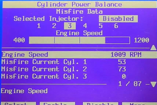
It is possible on most vehicles to perform a cylinder balance test with a suitably equipped scan tool. This test disables a fuel injector to measure the extent of which the idle quality changes or misfire changes or presents when goosing the throttle. The objective being to pick the cylinder that reacts differently with respect to the remaining cylinders. This was often able to be achieved by manually disconnecting the electrical connector on a fuel injector on older engines however. As well as being difficult/impossible to access all fuel injectors on a modern engine, it also has the potential to cause damage to engine management computers and/or injector drivers.
Another reason this method of testing may yield skewed or unclear results is due to the fact a modern engine management system may alter timing as well as other parameters to try and compensate for the misfire caused by disconnecting an injector.
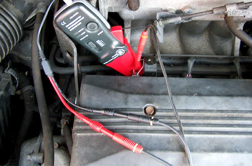
Another less common method for testing a fuel injector is to use a special tool to individually pulse an injector for a preset number of pulses and measuring the drop in fuel pressure in the rail. Again, picking the odd measurement/s is often indicative of the faulty injector/s however this test has it’s limitations. If a greater amount of rail pressure is lost you may conclude that the injector is leaking or failing to seal. If a lesser pressure is lost in the rail, there may be an interal blockage or damage to the injector. The integrity of the check valve in the fuel pump or other ancillary fuel system components must be checked to ensure accurate data from this test.
It should be noted that none of these tests are an exact science and fail to test the circuit driving the injector as well as the trigger coil within the injector.
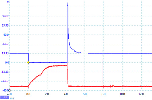
In the above image, the blue trace represents voltage across the injector and the red trace represents injector current
The Circuit Test
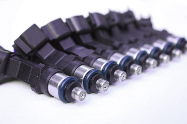
A typical injector only has one moving part; the pintle which resides in a chamber with pressurised fuel on one side and a nozzle on another. The pintle is fired by an electromagnetic coil.
As the electromagnetic coil is saturated with energy, the pintle moves back from the nozzle against a spring, allowing fuel to be injected into the cylinder.
In typical light vehicle applications, 12v is supplied to the injector which is switched to ground by a driver in the engine management computer and the voltage drops almost to zero. Failure to do so may be indicative of a poor connection in the wiring harness or an internal issue with the injector.

When the injector driver switches off, the pintle begins to close. The de-energisation of the electromagnetic coil in the injector creates a phenomenon called ‘reverse-EMF’ generated by the magnetic field collapsing in the coils which can result in a spike of up to 100v. This reverse-EMF is sometimes ‘quenched’ by use of a diode at the driver in an effort to prevent damage. When viewing the trace of a fuel injector on an oscilloscope, we often see this as as a flat peak.
This is often followed by a bump which represents the pintle meeting the seat of the injector when it closes. This may be more or less pronounced depending on the type of fuel injector.
Another valuable test to perform while we have an oscilloscope hooked up to an injector is to check that the waveform duration lengthens as ‘goose’ the throttle. This increase representing a higher demand for fuel.
The Current Test
When we observe the current waveform of fuel injectors, we can see a ramp that represents the injector coil becoming saturated with current. This begins as soon as the driver ‘switches on’ the injector.
There are two parts to this current ramp. The first being when the injector is closed while the coil takes time to generate enough electromotive force required to overcome the resistance of the spring holding the pintle on its seat.
The second being the point at which the pintle starts to move represented by a small rise in the slope of the trace. Again, this event and the level to which it is pronounced on a scope trace will depend on a number of factors with the main one being the construction and design of the fuel injector.
Using a scan tool paired with an oscilloscope allows us to assess a vital part of the fuel system by checking the health of both fuel injectors and their associated drivers.
If the Fuel Injectors do happen to be the issue, you can access a range of quality fuel injector service components here.
