Our customers don’t usually care if their vehicle is in ‘closed loop’ or not, but they do care when their check engine light is on or they are chewing through fuel like nobody's business!
Proper fuel control is important in order to maintain the correct air-fuel ratio supplied to the engine’s combustion chambers for ignition. Without proper fuel control, engine driveability and emission control can suffer. Fuel control provides easily understandable data that can be a valuable tool in diagnosing a driveability concern. The problem is, fuel control is often misunderstood and not used properly by technicians.

The Science
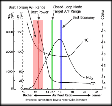
When petroleum is the fuel being used, the optimum or stoichiometric air-fuel ratio is 14.7:1, which means 14.7 parts of air to 1 part of petroleum. This air-fuel ratio will change with the fuel type: E85 fuel has a stoichiometric air-fuel ratio of 9.75:1, if the petroleum contains 10% ethanol the stoichiometric air-fuel ratio is 14.04:1. Today’s engine management systems are going to try to maintain the air-fuel ratio as close to stoichiometric as possible to keep the catalytic converter at optimal efficiency, limiting emissions and providing the best driveability to the driver. Catalytic converters function most efficiently when the exhaust gases coming from the engine are within about 4% of stoichiometry. But as we can see from the image above, the perfect air-fuel ratio isn’t always best for proper engine performance and operation. Acceleration requires a richer mixture (12.5:1 to 14:1 air-fuel ratio) for maximum power and the ECU may also request a richer mixture to prevent detonation under certain conditions. To maintain the perfect air-fuel ratio, the ECU will use a set of factory fuel maps stored in its database that will dictate how much fuel should be injected for a given load, rpm, temperature, etc.

Open and Closed Loop
The ECU will operate in two main fuel control modes: open or closed loop. During open loop, the ECU has limited feedback to achieve the proper air-fuel ratio, but when in closed loop the ECU will work continuously to stay as close to the proper air-fuel ratio as possible. The ECU uses the oxygen or lambda sensors in the exhaust to report whether the desired air-fuel ratio was attained when it is in closed loop. If the desired air-fuel ratio wasn’t achieved the ECU will decide what corrections are needed to correct the air-fuel ratio (this is fuel trim). The goal of the ECU is to maintain an appropriate air-fuel ratio and by using its fuel maps as a starting point, it will calculate the specific amount of fuel to inject. But engine wear, faults and parts issues can occur throughout its operational life and when this happens it will affect these calculations so adjustments are needed over the course of time. Fuel trim is the ECU’s adaptive strategy that allows it to deal with these issues by adjusting the amount of fuel that is injected into the engine, but only once it is in closed loop operation.

Short and Long Term Fuel Trims
The adaptive strategy of fuel trims consist of two main components: short-term fuel trim (STFT) and long-term fuel trim (LTFT). These terms are also known as additive for STFT and multiplicative for LTFT.
On V configuration engines there will be two complete sets of STFT and LTFT data that will pertain to each individual bank of cylinders, even some four-cylinder engines will have two sets of data separating the cylinders into pairs. Doing this provides better fuel control and also aids in diagnostics. STFT is the direct result of the feedback that the oxygen or air/fuel ratio sensors are providing to the ECU. This current, real-time information is used by the ECU to adjust the amount of fuel that is being injected into the engine. STFT adjustments happen almost immediately, but these changes are just temporary. LTFT is the accumulated information that is recorded over time. This historical information gathered from the STFT information is stored in a data file in the ECU known as fuel trim cells. These cells hold fuel trim information over a wide range of rpm’s and engine loads and are used by the ECU to make quick decisions when the engine load changes. LTFT is a slower reacting calculation that has no direct relationship to a lambda/oxygen sensor. Fuel trim numbers are displayed as a positive or negative value (+ or -). These values reflect the amount of change that the ECU is applying to the amount of fuel the engine is receiving as the ECU attempts to maintain the stoichiometric value of 14.7:1. Fuel trim information is of enormous value when it comes to many diagnostic decisions. OBD-ll fuel trim data can provide us with a starting point to diagnose issues and allow the correction of them, if we properly interpret the data and understand how fuel trim reacts to different situations. Lean codes and the driveability issues that accompany a lean running condition would be reflected with positive fuel trim numbers: an indication the ECU is adding fuel. In this situation we need to concentrate our efforts on why the lean condition exists. This may be due to a number of issues such as fuel pressure, false air, incorrect sensor data, vacuum leaks etc.
Rich codes and the driveability issues that accompany a rich running condition would be reflected with negative fuel trim numbers: an indication the ECU is subtracting fuel. Leaking injectors, broken fuel pressure diaphragms, improper fuel pressure and incorrect sensor readings are a few examples of issues that could result in a rich running condition. When observing the fuel trim data of a vehicle for diagnostic purposes, the total fuel trim of the engine must be calculated. Total fuel trim is an additive value: STFT+LTFT=Total Fuel Trim. On V style engines there will be a total fuel trim for each operating bank of the engine. Total fuel trim spread should also be looked at and should not exceed 10% (-5% STFT plus +5% LTFT= fuel spread of 10%). For many years the rule of thumb was +/-10% total fuel trim for most vehicles (European vehicles with traditional O2 sensors were lower at +/-5%). This value has changed with the predominant use of air-fuel ratio sensors that provide faster more accurate results on exhaust gas oxygen levels even during acceleration and deceleration. Today a better rule of thumb is tighter: +/-5% total fuel trim.
NOTE: Many manufactures are also using rear fuel trim to further fine-tune their fueling strategy. This information may show up in scan tool data and can affect overall fuel trims, but the base STFT and LTFT need to be addressed first.

The Real World
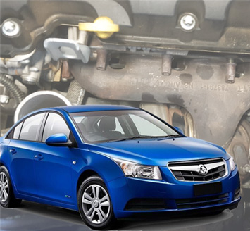
Here is a great example of where analysing fuel trim data assisted in the diagnosis and repair of an issue on a 2011 Holden Cruze 1.8L with 160,000km's on the clock.
The complaint was a rough idle, stalling at a stop and the check engine light illuminating. The car ran OK when cruising, but the customer wasn’t happy about the idle and stalling issues. The vehicle was scanned and a ‘P0171: System too Lean Bank 1’ code extracted. The freeze frame fuel trim data showed that the engine had been running lean when the code was set. The STFT was at +22% and the LTFT at +20%, and these trims were occurring at idle on a warmed-up engine. Adding STFT +LTFT = +42% of total fuel trim when the code was set; it was obvious the ECU was adding fuel to compensate for an issue. A good visual inspection was performed; there were no vacuum lines that were cracked, broken or missing and the engine’s intake duct was attached and not cracked leading from the MAF sensor to the throttle body. These engines are sensitive to un-metered air, loose oil filler caps and even a dipstick that isn’t installed properly or has a torn O-ring is enough to cause fuel trim and MAF codes on these engines, but a visual inspection had turned up nothing. At idle with the engine running in closed loop, the STFT and LTFT were both in the +20% area and the engine was missing, shuddering and running rough to the point the check engine light was flashing (although it hadn’t set any misfire codes). But both the STFT and LTFT returned to almost normal values when driving and accelerating, just as the customer had described. The information that had been gathered so far was indicating an issue with un-metered air in the form of a vacuum leak. Why? Because the fuel trims data is pointing in that direction... but it depends on the type of induction system the engine uses.
How does a vacuum leak affect a non-turbo engine’s fuel trim values?
During idle when the throttle plate is closed, the vacuum in the intake manifold is high and very little air flow is entering the engine, so even a small amount of un-metered air will have an effect on fuel trim. This forces the ECU to react to the lean condition with positive valued fuel trim readings. The fuel trims will return to almost normal during cruise and wide-open throttle when the throttle plate is open and there is little vacuum in the intake but lots of air flow into the engine. The small amount of un-metered air creating an idle vacuum leak is hidden or masked when the engine’s airflow increases, so the effect on fuel trim is less evident.
How does a vacuum leak affect a turbocharged engine’s fuel trim values?
The use of a turbocharger changes the way an intake leak will affect fuel trim. If a turbo-charged engine has a vacuum leak after the throttle plate, the fuel trim numbers will be positive at idle (like a non-turbo engine), when there is no boost and a vacuum in the intake. But when the engine is in boost mode and positive pressure is provided in the intake, the vacuum leak will allow boost air to escape. This causes the fuel trim numbers to become negative during a boost situation. This happens because the ECU is supplying fuel for the amount of air the MAF sensor.
| Idle | Cruise | WOT | |
| Vehicle Speed | 0hkm/hr | 60km/hr | 100km/hr |
| STFT | 20% | 5% | 4% |
| LTFT | 21% | 1% | 1% |
| Engine Load | 11% | 50% | 100% |
This chart shows the STFT and LTFT values of the vehicle before the repair. Because all that air isn’t being supplied into the cylinders, the ECU is supplying too much fuel, creating a rich mixture. The fuel trims will react with a negative value. Suspicious of an intake leak, a smoke machine was connected to the intake, but the intake was not the issue, neither was the brake booster or the hose. The diaphragm in the PCV oil separator assembly had ruptured, allowing full manifold vacuum to enter the engine. The PCV is integrated into the rocker cover and is not serviceable, so a replacement rocker cover was ordered and installed. The fuel trims were reset and the vehicle road tested to verify the repair.
Conclusion
For some reason, lean conditions seem to be more common in vehicles presented to today's workshops. False air from internal rocker cover PCV systems, especially on European cars, has become a frequent issue as well as purge solenoids that will leak vacuum after they have passed the actual OBD-ll purge leak test, and will be closed when you are testing them. Verifying that a vehicle is in fuel control is important and looking at the fuel trim values can be a valuable diagnostic tool to find driveability issues. Using total fuel trim and fuel spread can point you in the proper direction for a successful repair that will restore the vehicle’s driveability and its emission controls.