
SRS systems (Supplemental Restraint System) or SIR (Supplemental Inflatable Restraint System) as they are known in GM-speak, is a veritable minefield for many technicians, and we have all heard horror stories of technicians getting hurt when airbags are deployed accidentally or inadvertently while performing servicing and maintenance on these systems. However, airbag systems are not all that complicated, and while there are rumours floating about that only factory-trained technicians using factory tools should work on these systems, the truth is that many SRS servicing and maintenance procedures can be carried out successfully without the use of factory-grade scan tools. In this article then, we will take a closer look at some common airbag-related issues, and how to resolve them safely without factory scan tool tools, starting with this question-
As a practical matter, it would be a mistake to underestimate the complexity of modern SRS systems, but when these systems are viewed objectively, they are no more complicated than an average, standard engine management system.
This is saying a lot, but if you have not had much exposure to SRS systems and their issues, it helps to think of them as systems that have inputs, outputs, and control modules that create outputs based on inputs from various dedicated sensors placed at strategic positions around a vehicle.
It is also helpful not to think of SRS systems as stand-alone systems. The fact is that while all SRS systems are composed of a network of impact-sensitive sensors, sensors that “weigh” seat occupants, switches in seat belts, seat belt pre-tensioners and explosive devices that inflate the actual airbags, all of these components are controlled by one or more control modules that are linked to other safety systems such as the ABS -, stability control -, and others.
Therefore, a SRS system may be only partially activated during a potentially dangerous situation. For instance, the stability control system may identify a skid, which may activate only the seat belt pre-tensioners (without inflating or deploying air bags) in order to hold occupants in their seats securely. There are other possible examples, but the point is that a SRS system is an integral part of a vehicle’s overall ability to mitigate, if not to prevent, possible injuries to occupants during a crash.
As a result, car manufacturers have developed programming that runs several kinds of self-tests on SRS systems at different points during a trip. We need not delve into the complex algorithms that determine whether or not all parts of an SRS are fully functional here; suffice to say that most faults, defects, or malfunctions in SRS systems use one-trip detection logic, and that all faults, failures, or malfunctions in an SRS system will set fault codes and trigger warning lights, which begs this question-
For the most part, SRS systems are fairly robust, and even without any routine servicing most SRS systems will function as expected during a crash. However, as with any complex automotive system that communicates with other systems over intricate wiring systems, SRS systems are not immune to faults, failures, and malfunctions.
Moreover, some types of failures are more common on some applications than others are, but while component failures are relatively rare, failures involving bad connections as the result of poor design and/or corrosion as the result of poor placement of some components are very common. We will discuss some of these common issues in the following section, but to avoid confusion, we will divide these issues into two groups, input issues and output issues, starting with-
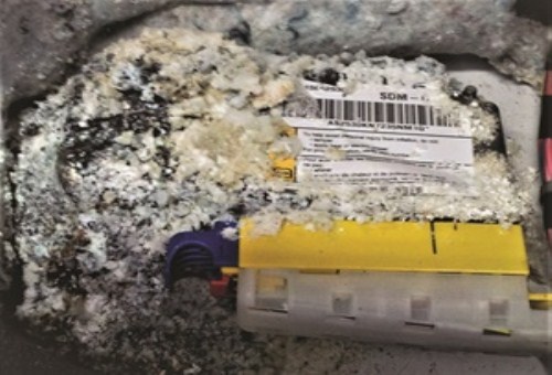
Image source: https://images.autoserviceprofessional.com/post/M-photo-3-8-1.jpg
The image above shows corrosion of an SRS control module as the result of a leaking windscreen, and in practice, many SRS input faults and failures such as this one can be diagnosed with a non-factory, but fully updated high-end scan tool and a high quality multimeter that can measure volts, currents, and ohms. Note that if your up-to-date scan tool can extract SRS fault codes, it can likely also clear the same codes, so let us start with-
Code B0084-00 on GM and related makes/models
GM trucks from the 2007 to 2014 production years are plagued by corrosion of their front crash sensors, due to lack of protection against water splashing onto the sensors. Nonetheless, when code B0084 is set, the SRS warning light will flash seven times before illuminating permanently. Note though that code B0084 is only the basic code, and that one of several suffixes can be present, with 0F, 39, 3A, or 71 being the most common suffixes.
However, if the suffix “00” is present, you need to inspect the right front crash sensor. In most cases, corrosion will be obvious, but if it is not, swop the sensors around to see if the right-hand sensor generates a code on the wiring of the left-hand sensor. If it does generate the same code with the same suffix, the sensor must be replaced, but if it does not, the problem involves a resistance or continuity issue in the right-hand sensor’s wiring. Note that front crash sensors on GM are trucks can be replaced on a plug-and-play basis, so no programming or integration is required. All that is required after a front crash sensor replacement is clearing of the code with a scan tool.
Code B0084-39 on GM and related makes/models
Another common code on GM and related products is B0084-39 – “Internal Sensor Failure”, which may or may not be caused by corrosion in the front crash sensor’s electrical connector. One way to test for poor contact is to swop the front crash sensors; if the affected sensor generates the same code with the same suffix on the other side, the sensor has failed internally, and it must be replaced.
However, with this code it is imperative to check all connectors for evidence of corrosion, but note that replacement of the connectors might not always solve the problem. The only reliable, long-term remedy is replacement of the relevant wiring harness to ensure that all electrical values fall within the ranges specified by the manufacturer, which ranges can often be found online.
Code B0085/B0086 on GM and related makes/models
These codes are defined as “Left front side impact sensor”, and “Right front side impact sensor” respectively, and they refer to the side impact crash sensors in the front doors. Note though that the basic codes can be followed by any one of several suffixes, with suffix 39 (Internal Electronic Failure) being the most common. Other suffixes include 02, 05, 0F, 3A, and 71.
Although the suffix “39” refers to an electronic failure, the most common cause of this code is more often than not, a wiring failure (where the wiring from the doors enters the “A” pillar) as a result of the wiring flexing every time the doors are opened and closed. The fix in this case involves finding and repairing the broken wiring between the door and the “A” pillar.
Code B0084-39 on Honda Civic models
Honda Civics from the 2001 to 2006 production years are plagued by the failure of a tiny 3-wire switch in their seat belt buckles. The function of this switch is to let the SRS system know if seat occupants are wearing seat belts; thus, a failure of this switch will trigger a warning light, and set code B0084-39, which is defined as “Driver’s seat belt buckle switch”.
Diagnosing this code involves checking for specified voltages at the seat belt buckle, which voltages should be the following-
Note that if these voltages are not found, or are outside of these ranges, the correct course of action would be to replace the relevant harness, since Honda does not approve of repairs made to the wiring of their SRS systems, and especially so if there is corrosion present in any part of the wiring.
Most, if not all SRS output issues can also be diagnosed with a high-end, but fully updated non-factory scan tool, a high quality digital multimeter, and reliable service information, which is relatively easy to find online. Excellent sources of service information include the discussion group(s) of websites like mechanic.com.au, or one of the many discussion forums that are dedicated to specific vehicle makes and models.
Nonetheless, SRS control modules monitor all associated circuits and modules continuously for correct operation, as well as for the presence of short circuits to both B+ and ground to ensure that the system will perform as expected when the need arises.
However, since most, if not all air bag inflator circuits are typically of the two-wire type, it is common to find resistance issues in these circuits. Both low and high resistances will set codes and trigger warning lights, so note that in terms of resistance, all inflator circuits typically operate in the 2 Ohm - 3 Ohm range, and any high-end scan tool will readily display this data, although late model Mazda models operate in a wider, 0.8 Ohm to 9.85 Ohm range.
Although the preferred (by manufacturers) method of testing inflator circuits is to use equipment that can simulate electrical loads/resistances, it is possible to do the same thing with reliable service information and a few 1 Ohm, 2 Ohm, and 3 Ohm resistors- the last of which will work fine on new Mazda models.
Bear in mind though that substituting a test resistor for a suspect resistor requires up-to-date service information to prevent accidentally deploying one or more air bags. So, assuming that you have the required service information available, simply substitute the suspect resistor with a test resistor, and clear the codes. If the code does not return, the fault is typically in the inflator itself. If however, the code does return, the fault is typically in the wiring, or in one or more control modules, which will require a purpose-built diagnostic strategy to find and repair, but below are some details of common faults that are relatively easy to repair-
Code B2292 on 2005 – 2009 Ford Escape models
This code is defined as “High resistance in the passenger side seat belt pre-tensioner circuit”, and is very common on effected models. The problem almost always involves a bad connector in the passenger side pre-tensioner circuit, but in many cases, simply disconnecting and reconnecting the connector will resolve the issue. If this does not work, replace the OEM resistor with a 2-Ohm test resistor. If the code returns immediately, you will need to find the source of the high resistance, which more often than not, is across a slip joint in the affected pre-tensioner’s wiring harness.
Code 27-10 on Honda Civic models
In Honda-speak, the presence of this code indicates an open circuit in the driver’s seat belt pre-tensioner, and although Honda recommends using an inflator simulator to diagnose this code definitively, fitting a 2-Ohm test resistor will accomplish the same thing. Clear the code after installing the resistor, and if it does not return immediately the belt pre-tensioner is defective, which is the case in nine out of every ten instances of this code on affected models.
Note though that if the code does not clear with the test resistor installed, you will need up-to-date service information to devise additional testing strategies.
It should be noted that most SRS control modules are single-use modules that must be replaced after a collision had occurred that caused one or more air bags to deploy. The problem with this is however that almost all SRS control modules in use today require the use of factory scan tools and proprietary software, since these controllers need to be set up, calibrated, and programmed after replacement. In fact, most GM control modules come with no programming except for a kind of power shell, into which vehicle-specific programming must be loaded.
In some cases though, such as with GM SRS systems, the information and/or software is available via a subscription-based internet service. Ford, Honda, and Toyota offer a similar service, but in all cases, a factory-level scan tool is required. For this reason, it is crucially important that you know and understand the capabilities and limitations of your non-factory scan tool before you commit to replacing SRS control modules.
Note that attempting to reprogram a SRS module with unsuitable equipment will not only damage the replacement SRS control module (and possibly one or more other control modules on the vehicle), but the attempt may also damage the unsuitable scan tool.
Even though SRS systems are safety critical, life-and-limb systems, there is no need to turn away SRS-related business just because these systems are perceived to be overly complicated and difficult to work on. The truth is that SRS systems are no more complex than engine management systems, and if you can use your knowledge of circuits (and how to test circuits) to diagnose engine management issues, there is no reason why you cannot use that same knowledge to diagnose and fix SRS issues.
It might take you a while to find the relevant service information, but the upside is that there are many online sources that publish SRS service information, the most comprehensive of which is available here- https://www.nastf.org/i4a/pages/index.cfm?pageid=3292, but note that access to some services offered requires a subscription.
