The mechanic.com.au website features many articles that deal with the intricacies of electrical theory and diagnostics, as do many other online resources. In fact, articles and guides that cover all aspects of the importance of having a sound understanding of the electrical systems one is diagnosing, as well as the need to develop a viable and logical diagnostic strategy abound. However, while these kinds of resources can be extremely informative and useful, there is one thing in particular that many of these types of articles do not mention, this thing being the fact that the integrity of OEM electrical connections often leaves much to be desired.
Put differently, his means that our diagnostic strategies are often tripped up by the little things; things like connectors that have been pulled apart one time too many, poorly crimped terminals on any of thousands of wires, or as often happens, intermittent issues caused by poor or incorrect back probing practices during previous repair attempts. In practice, the “little things” can take many forms apart from the ones mentioned here, so in this article, we will take a closer look at automotive electrical connectors and their terminals, in terms of why they fail so often and so easily. Let us start with stating-
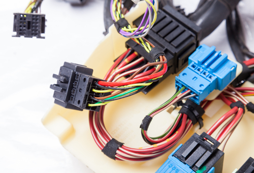
Connectors such as the example shown here offer us, as technicians, an easy and convenient way to isolate components or to test wring for continuity etc. However, connectors present car manufacturers with serious problems, not the least of which is the cost of producing complex connectors, which must be seen against the background of the connector manufacturer’s ability to manufacture a specific connector.
As a practical matter, car manufacturers don’t make electrical connectors. Most of the connectors in a standard wiring harness are made by specialist contractors/manufacturers, and so for the most part, car manufacturers use “off-the-shelf” connectors in most harnesses. In special applications, however, a car manufacturer might require a special connector design for a specific purpose in which case, the complexity of the connector is limited by both the cost, and the engineering challenges involved in making the connector.
Special applications aside though; most off-the-shelf electrical connectors represent a compromise between reliability and cost of production, with the cost being a function of the engineering challenges in producing the connector. While this is true of most car parts, the problem with electrical connectors is that reliability comes in at a distant third place- far behind cost and manufacturability.
Note, though, that this is not the same as saying that electrical connectors supplied by reputable manufacturers are designed to fail. Far from it: considering the extreme temperature swings, vibrations, the presence of oil and fuel vapours in the average engine compartment, and the fact that many connectors are subjected to moisture and dust for extended periods, most connectors do a remarkably good job of maintaining electrical continuity in most harnesses.
Having said that though, consider his statement by a major supplier of electrical connectors to the global automotive manufacturing industry-
“…in general, Delphi components are validated to perform to specification after 10 engage/disengage cycles. Some components may have a slightly higher number of cycles specified in their design specifications. We need to know which component family, or families, the customer is referring to in order to be more specific. However, in actuality, you probably wouldn't see any degradation of the electrical interface of Delphi connection system components until beyond about 50 engage/disengage cycles (barring any physical damage). Some newer product families may have even higher engage/disengage cycle durability; these may primarily be designed specifically for the Commercial Vehicle market.(Italics added for emphasis)
“In summary, most Delphi Connection Systems are not intended for applications that necessitate multiple numbers of engage/disengage [cycles]. Please contact us to discuss your application for more information.” (Italics added for emphasis)
The operative words/phrases in the above section of a technical FAQ published by this manufacturer include-
While the above phrases may appear to be used selectively to cast the products of this manufacturer in a bad light, this is not the case, because the above quote/extract is taken directly from a technical resource that was published by the connector manufacturer, but what does it mean for us, as technicians?
It simply means this- we can never be sure that any given connector will not fail to operate to specification after a few, or even a single disengagement/engagement cycle. In short, any given connector may continue to work as expected after several disengagements, or it may not. The manufacturer cannot guarantee that it will, though.
Moreover, we have all seen overheated and otherwise damaged connectors, which adequately fulfill the "physical damage" requirement. In addition, any back probing of wiring, no matter how carefully performed, can potentially damage silicone water and dust seals, meaning that we often, albeit inadvertently, create physical damage to connectors during diagnostic procedures.
So, given the above, it would be tempting to think that electrical connectors would work flawlessly for the life of the vehicle if they are -
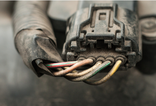
- this would be a tempting thought, but real-world operating conditions subject electrical connectors to these kinds of conditions more or less continually, which usually, but by no means always, lead to visible signs that a connector has failed. These kinds of failures are easy to spot- connectors are usually swollen, discoloured, or melted, depending on the nature of the failure.
The invisible kinds of failures are somewhat more difficult to identify. Continuity and resistance issues across connectors can occur even on brand new harnesses, as this writer once saw for himself when he worked in the BWM factory in Southern Africa some years ago. During this time, the factory produced one car every seven minutes*, and this writer’s job was to find out why some new cars would not start during the final stages of assembly.
*This factory’s output has increased significantly over the intervening years, and no-starts are now automatically diverted to a team of specialist diagnosticians that are allowed more than seven minutes to investigate and resolve no-start issues.
With only seven minutes to do this before the next new car arrived at his station, this writer soon learned to identify certain patterns on harnesses made by different suppliers. While some no-starts resulted from poorly engaged engine harness connectors, or engine harness connectors that were not engaged at all, some models failed to start when one or two specific connectors on certain harnesses failed. Bear in mind that all harnesses were tested for continuity* before being installed into vehicles, and those that failed on the test bench were obviously not installed.
*The test bench was later improved to simulate the exact loads all connections would carry while in actual use. While this improvement dramatically reduced the number of no-start conditions on newly built vehicles, it also caused a dramatic increase in the number of new harnesses that failed the bench test.
We need not delve into the complexities of testing BMW wiring harnesses in seven minutes (or less) here, beyond saying that it soon became obvious that some wire terminations in some connectors failed in a vehicle when they were loaded for the first time. This observation implies that if a wiring harness does not fail immediately upon its first use in an actual vehicle, it will likely only fail when routine maintenance/servicing/diagnostic procedures or environmental and/or operating conditions induce/cause a failure.
The above is saying a lot, so let us look at the most common types of connector failures, starting with-
The biggest problem we have with connectors is the fact that we just don’t know how much force it should take to engage/disengage the two parts of the connector. This is not idle speculation, because the manufacturers of connectors specify the number of times a connector can be engaged/disengaged before it could start causing issues.
Consider the example connector above, which connects a large number of conductors. With such connectors, we can never be sure how much of the force we apply to engage the two halves is taken up by the male and female terminals engaging, or how much of the force is taken up by friction between the location devices in each half, or by overcoming the resistance of latching/locking mechanisms.
We have all had occasion to use sideways rocking movements to disengage some connectors, and in these cases, there was no telling how much damage the violent sideways movements did to a) the terminal securing tabs, whose function it is to hold the terminals in place in the connector, and b), the terminals themselves. Thus, when re-engaging the connector after having inspected it, we may not be aware that one or more female terminals in the connector had lost their “grip strength” on their male counterparts.
If we are particularly fastidious, we may test for continuity across individual connections, but if the truth were told, we most commonly just reengage the connector and continue to look for the problem elsewhere if we don’t see anything obviously wrong with the connector. However, here is the thing; by violently tugging on the halves of the connector, we may very well have created potential problems, the most common being an intermittent loss of contact, or high resistances through damaged terminals.
Connector manufacturers are well aware of the fact that simply disengaging a connector can damage it, hence the specified number of safe engagement/disengagement cycles for each connector design they produce. However, nobody has as yet developed a tool that can measure the engagement/ disengagement forces being applied to all connectors under all conditions, so the best thing to do is to a) not disengage connectors unless it becomes absolutely necessary, and b) to take extreme care not to apply sideways forces to any part of a connector while disengaging it.
This writer would suggest that the best way of testing connectors is to perform voltage drop and continuity tests across individual connections when the affected or suspect circuits are loaded with their maximum allowable voltages and/or currents. Substituting headlight and other light bulbs for the regular electrical consumers in a circuit might involve some additional work, but the upside is that you can almost always avoid causing damage to connectors by not disengaging them needlessly.
Also known as “terminal fretting” micro corrosion is not only less common than the usual green corrosion we often see on connector terminals, it is also almost impossible to see without using a microscope, hence the term, micro corrosion. As a point of interest, severe or extreme cases of micro corrosion might be visible on terminals when using a strong magnifying glass, but a casual, naked-eye observation or inspection will typically not show evidence of any kind of damage or corrosion.
Under a microscope, this type of corrosion consists of microscopically small pit marks that are most commonly caused by high-frequency vibrations or relative motion between two terminals. This condition can sometimes be caused by connectors that are not properly secured, but in most cases, micro corrosion results from female terminals having lost their “grip strength” on their male counterparts because the connector had been disengaged too often.
The most common symptom of micro corrosion is an intermittent loss of contact across individual connections in the connector that can often be resolved by disengaging and re-engaging the connector several times. However, since the original problem was almost certainly caused by disengaging the connector too often, doing this is usually only a short-term solution- if it works at all.
So, how do you know you are dealing with micro corrosion if you can’t see the effects of the corrosion or fretting? Well, this is not always easy, but one sure way to eliminate the possibility of micro corrosion being the cause of intermittent connection issues is to apply a small drop of something called Stabilant 22a to each terminal.
As a practical matter, Stabilant 22a is not an electrical cleaner, although it does have some cleaning properties. The primary function of this solution is to lay down a thin film of extremely conductive polymers between contact pairs that not only stops micro corrosion from progressing, but also actually enhances the electrical conductivity of contact areas between terminals, switch points, and the like. However, since Stabilant 22a was originally developed for use in the aviation industry, it is little on the pricey side, but one small bottle (30ml) of the stuff should last you at least a couple of years. We highly recommend this product because it works as advertised.
Note that since Stabilant 22a contains highly volatile alcohol-based compounds, most online retailers outside of Australia won’t ship it here by air. However, Stabilant 22a is available from this local online retailer.
Image source: https://www.youtube.com/watch?v=ZLUcmsxk3qg
Sometimes, and especially when we are working under severe time constraints, it can be easy to take the easy way out and simply pierce wires with a sharp instrument (including with purpose-made piercing probes) to obtain test readings. However, while this can save time in some situations, this screen grab from a video shows the effects of failing to repair the wiring properly afterwards.
In cases like this, it could potentially take longer (and cost more) to repair the comeback than it took to resolve the original problem. Thus, what do you do when you need to test continuity across a connector, but you don’t own a proper set of back probing needles, and you also don’t want to risk damaging the connector by pulling it apart? Luckily, there is an easy, cheap, safe, and effective workaround solution, so consider the image below-
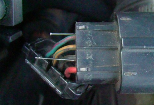
Image source: https://honda-tech.com/forums/honda-accord-1990-2002-2/p0715-97-accord-3277474/
This method has worked for this writer on many occasions. In this example, a simple sewing needle and a pin serve as back probing needles to test a MAF sensor connector on a Honda application. To the purists among us, this solution might appear ridiculous, but is using pins and needles really a silly idea if it works?
This writer does not think so, because pins and needles have some very distinct advantages over traditional (and expensive) back probing needles. For one thing, they are exceedingly cheap and freely available, and secondly, pins and needles are thin enough to pass between the silicon seals and the body of the connector without damaging the seals in any way. Moreover, pins and needles are not long enough to reach the part of the terminal that engages with its opposite part. Consider the image below-
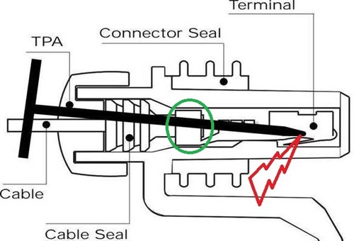
This diagram shows a T-pin* being used as a back probing needle, but in this case, the needle was long enough to reach the engagement area of the terminal, which if it happens, almost always reduces the "grip strength" of female terminals, which has serious negative consequences for currents flowing through the terminal pair.
* Lately, it seems that T-pins, which are primarily designed for use in the textile industry, has become the rage among large numbers of mechanics, who use them as back probing needles probably because T-pins are a whole lot cheaper than high quality, purpose-designed back probing needles.
In this example, the point of the pin should have come to a stop against the terminal at any point in the green circle, but because T-pins are typically not only much thicker than proper back probing needles but also more pliable, the pin passed right through the silicone seal to reach the terminal engagement area. In this example, the T-pin did not only damage the silicone seal but also the terminal, and both issues will almost certainly result in electrical issues in that connector at some point in the near future.
Nonetheless, performing back probing correctly is as much as an art as it is a learned technique, and both art and technique become considerably more difficult when suspect connectors are hard to reach or access. In such cases, perforating the insulation wires might be the quickest, if not always the best option to take readings. However, if you have to pierce wiring, please do not use multimeter probes or a piece of baling wire sharpened on a grindstone, because both “tools” will damage and/or break wire strands in the conductor. Instead of blunt instruments, this writer recommends that you use a proper piercing probe that will make the smallest possible hole in the insulation.
All high-quality piercing probes have sockets on their ends that accept most multimeter probes, meaning that is easy to work the sharp end of the probe into the wire only until the meter registers a reading. This typically does not break or separate wire strands, and repairing the hole in the insulation also becomes easier.
However, this writer does not recommend using electrical tape to cover holes pierced into wiring insulation. Although tape may work well for a while, heat, moisture, vibration, and dust all work against tape remaining an effective seal. Based on personal experience, the best ways to seal perforations in wiring insulation reliably include applying a small dab of sensor-safe RTV silicone or even a dab of high-quality clear nail varnish over the hole. In both cases, however, all traces of grease, oil, dust, and moisture must be removed from the wire to be repaired for the best results, which leaves us with this-
We hope that this article has given you some new insights into both the possible causes of at least some electrical issues and how to avoid them. However, this writer would be the first to acknowledge that it is not always easy or possible not to disturb wiring harnesses and the connectors that hold them together, but if you have to disengage connectors, be sure to do it as gently as you can.
Somewhat counter-intuitively, taking things slow and easy might reduce the time you spend chasing down an electrical fault, because by taking your time (within reason, of course), you can largely prevent causing damage to wiring and especially to connectors, where there was no damage before.
