Since we all have different strengths and weaknesses, the term “non-diagnosticians” in the title of this article was deliberately chosen for two reasons. The first reason is to differentiate between those among us who specialize in using all of the advanced functions of modern scan tools to diagnose extremely challenging electrical issues or to do module programming, and those among us who only use some of the basic functions of scan tools to diagnose and fix more mundane, run-of-the-mill issues such as misfires or hard starting concerns.
The second reason is perhaps more pertinent, since those among us who mainly use the basic functions of scan tools may perhaps not be aware of how advanced and user-friendly even generic scan tools have become in recent years. Of course, this does not mean that those among us who don’t specialize in advanced electronic diagnostics are somehow inferior mechanics; far from it, but the fact remains that there are many mechanics among us who do not use scan tools to their best effect.
There are many reasons why this is so, but we do not need to discuss those reasons here, except for the one time when this writer recently observed a young mechanic trying to extract fault codes from a well-used Toyota Land Cruiser by furiously turning the key on and off while stomping on the brake and accelerator pedals. As he (the young mechanic) put it at the time, he did not think their workshop’s computer box “…did fault codes on 2019 diesel Land Cruisers”, hence the furious “key-dance”.
This display of ignorance (or desperation, depending on your point of view) was painful to observe, so this writer offered to see if the small workshop’s “computer box” could find some fault codes. It turned out that the “computer box” was of a reputable brand, and only about four years old (but hardly used), and it found some DPF-related codes with no trouble at all.
This is admittedly an extreme case that occurred in a small and extremely remote workshop, but even so, this level of ignorance of what scan tools and even older generic scan tools can do, was rather instructive, given the imminent implementation of the Competition and Consumer Amendment (Motor Vehicle Service and Repair Information Sharing Scheme) Act 2021.
Therefore, with the future in mind, this article will focus on how the new generation of scan tools can help us to both understand, and diagnose issues with the rapidly developing technology in new vehicles. Before we get to specifics, though, let us take a quick detour to see-

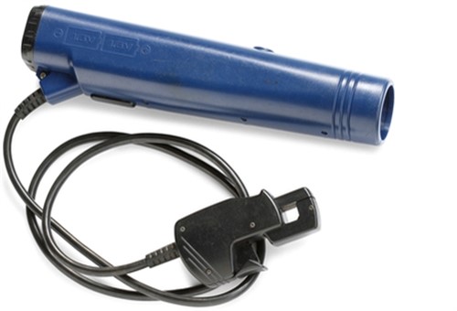
Things were really simple when this writer started his career as a mechanic in the late-1970s, and the oldest among us will remember this time as a period when the most advanced diagnostic tools we had (or needed) were inductive timing lights such as the example shown here that incorporated a dwell angle meter and perhaps a tachometer. Other tools of the trade in the ancient days included a set of vacuum gauges with which to tune and synchronise multi-carburettors, an analogue multimeter, and a variety of test lights. If one really wanted to live on the cutting edge of diagnostics, one invested in a three-gas exhaust gas analyzer and a set of “see-through” spark plugs that allowed one to see the colour of the combustion flame. Generally speaking, an orange or red combustion flame was bad, while a blue-ish combustion flame was good, although this was sometimes very difficult to achieve with some types of side-draught carburettors that produced extremely rich air/fuel mixtures.
In addition, in those far-off days, one could buy copper spark plug wire by the metre, as well as brass terminals with which to make up new spark plug leads. Off course, these spark plug leads required the use of suppressors to prevent electromagnetic interference on all car radios in the immediate vicinity, but one could find these suppressors at any parts supplier. Not that all suppressors worked equally well, but if one set did not work as well as expected, one just replaced them with a different brand.
Diagnostics were equally as uncomplicated. Circuits were simple, and it was rare to find more than two consumers on a single circuit, meaning that simple voltage drop tests usually sufficed to find issues. Moreover, electrical consumers were hardwired into their supply circuits, which meant that it was easy to trace circuits from end to end.
However, this easy life could not continue, and things became significantly more complex with the near-universal introduction of electronic fuel injection, ABS brakes, and the first iterations of electronic engine/fuel management systems in the early to mid-1980s. We need not spend too much time on this topic, but here is a short history of electronic control systems before 1996, when OBD II systems became mandatory.
In many ways, General Motors can be said to be the leader in the (forced) race to develop electronic engine management systems with self-diagnostic capabilities. For instance, the three major developments listed below can all trace their origins back to General Motors, so let us start by looking at-
ALDL - (Assembly Line Diagnostic Link)
Although this system was originally known as General Motors’ (proprietary) Assembly Line Diagnostic Link, several major manufacturers ended up using some variation of it. In short, this interface was made to suit the capabilities of a particular engine management ECU, and as a result, ALDL systems did not only have different capabilities, but also different communication speeds and pin-out configurations.
While most ALDL systems communicated at a rate of 160 bits per second, some advanced ALDA versions could communicate at speeds of up to 8192 bits per second, which was lighting fast for the electronics of the time.
OBD I
Although the principal driving force behind the adoption of OBD I was a need to reduce exhaust emissions over the useful life of a new vehicle, the problem with this requirement was that it did not call for at least a measure of standardization among vehicle manufacturers in terms of both system capabilities and implementation.
Moreover, since enforcing the implementation Of OBD I relied on compulsory annual testing to determine whether the OBD system is working or had been tampered with, the lack of uniformity in how various manufacturers made their systems work, and what these systems monitored/reported, made it impossible to develop a set of evaluation criteria that could determine whether or not a given vehicle passed an emissions test.
Worse, though, OBD I was a complete nightmare for mechanics in terms of diagnosing faults. In theory, manufacturers had developed simple fault codes, but the problem was that manufacturers generally made these up as they went along. Limited space precludes a discussion on this very confusing state of affairs, beyond saying that this writer still has work orders from this time that list at least seven different trouble codes for the same fault on seven different vehicles.
From a diagnostic perspective, this was not the biggest problem with OBD I: the biggest problem was actually extracting the fault codes. For instance, on (among others) Honda and Nissan vehicles, one had to count the number of times a little red (sometimes green) light on the ECU flashed- if it flashed say ten times without significant pauses between flashes, one looked up the number 10 on Honda's list of fault codes, with the number "10" corresponding to a specific trouble code. However, these lists sometimes changed when manufacturers upgraded one or more ECUs, so unless one checked with the dealership, one was never sure that one was dealing with the correct trouble code.
By way of contrast, GM forced one to extract fault codes by initiating a “diagnostic mode”, and manipulating the climate control systems' controls to display stored trouble codes on a primitive LCD screen. As with Honda vehicles, these codes and their definitions also sometimes changed when ECUs were upgraded, so in both cases, mechanics sometimes spent more time verifying that they were dealing with the correct codes than they spent on diagnosing and fixing stored trouble codes.
The only vehicles during this time that used an early version of live data streaming were some Toyota and Lexus models, but this could only be accessed with a primitive kind of code reader/scanner that few independent workshops or mechanics had access to at this time.
OBD 1.5
The major confusion that came with the introduction of OBD I systems was not lost on regulatory authorities, and particularly not on the SAE (Society of Automotive Engineers) which is based in the USA.
Thus, starting in about 1991, this organisation began work on developing a standardised set of trouble codes (now known as generic codes), automotive terms and abbreviations, as well as standardised locations for components such as oxygen sensors, catalytic converters, and cylinder numbering schemes.
Among car manufacturers, though, General Motors saw the advantages this scheme held, if only from a marketing perspective, so by 1994, GM started implementing parts of this new scheme, which we now know as OBD II. At the time, however, the partial implementation of OBD II became colloquially known as OBD 1.5, although no manufacturer at the time referred to it as such.
In practical terms, however, GM started adopting some standardized trouble codes to indicate issues with standard or common issues. For instance, in 1994/95 Corvettes, GM applied the codes P0116-P0118, P0131-P0135, P0151-P0155, P0158, P0160-P0161, P0171-P0175, P0420, P1114-P1115, P1133, P1153, and P1158 to (issues with) the downstream oxygen sensor on the catalytic converters of these vehicles. In practice, these same codes still apply to the same oxygen sensor on all GM vehicles, and the downstream oxygen sensor on all other makes and models. Nonetheless, it was only after the mandatory introduction of OBD II in 1996 that all manufacturers were obliged to apply the same generic trouble codes and their standardized definitions to the same generic problems*, which brings us to-
* Note that this only applies to vehicles that are made and sold in the United States. In fact, this requirement is embodied in the SAE J2021 Standard (as revised over the years), which is in its turn, embodied in an Act of Congress- the full details of which can be accessed here, and here.
Light vehicles not produced in the United States, or vehicles that are not intended for sale in the United States are not legally required to follow the prescripts of the SAE J2021 Standard. Nonetheless, the fact is that for the sake of uniformity, if nothing else, all major vehicle manufacturers in all major markets, except for some manufacturers in China who make vehicles strictly for the Chinese market, do adhere to this standard in terms of how they allocate fault codes and implement exhaust sensor locations.
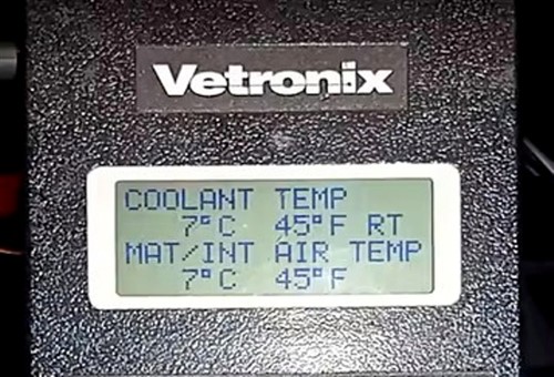
Although the introduction of OBD II in 1996 represented a major revolution in how mechanics across the world approached diagnostics, the fact is that the scan tools of the time lagged far behind the technology and systems on vehicles they were designed to interrogate. Consider the image below-

This image shows the entire display screen of a scan tool made by Vetronix in 1995 when GM was already implementing parts of the nascent OBD II system. However, while this example of a GM Tech1 factory scan tool, and others like it, were at the cutting edge of diagnostic technology in the mid to late 1990s, the tools of this era suffered from severe limitations.
For instance, tools from this era in general, and this example in particular, had no graphing capabilities since their refresh rates were only about 10 000 bits per second*, compared to the more than 50 000 000 (and often more) bits per second refresh rates of the high-end generic scan tools that are available today.
*When used with GM’s proprietary UART (Universal Asynchronous Receiver/Transmitter) communications network.
Nonetheless, even with their lack of graphing capabilities and generally low communication speeds, scan tools of this era did manage to diagnose vehicles of this era successfully, although if the truth were told, most mechanics, including this writer, dreaded using these tools. The main reason for this was not so much the fact that scan tools of this era required external power sources and ground feeds* to work, but because it was extremely difficult, confusing, and time-consuming to navigate between these tools' various functions.
*Often obtained from the cigarette lighter socket, but more commonly, directly from the battery via suitable jumper leads.
We can list many examples of how the severe limitations of early scan tools made diagnostics more difficult than it needed to be, but one example will suffice-
By the late 1990s, GM vehicles already used up to eight separate control modules, all of which were interconnected by some early version of a CAN bus system, which, incidentally, were all extremely susceptible to electronic noise. So, one day, this writer was presented with a (GM) vehicle in which the instrument cluster lights flickered severely when the headlights were switched on.
The GM Tech1 scan tool showed a total of 12 fault codes in four control modules, with the body control module boasting a total of six codes, and that was where the usefulness of the scan tool ended. It could not test each individual CAN bus line, and it offered no ability to "split" the CAN system into its constituent parts, which would have helped interrogate each implicated control module in isolation.
In this case, then, there was no other option than to disconnect each implicated control module from the CAN system in turn before testing to see if the problem persisted. In the end, this process took more than a full working day, and the problem eventually went away when the body control module was disconnected. Tracing all the components and electrical consumers that were connected to this module took up most of the next day, and by a slow process of elimination, this writer eventually discovered that the problem was caused by cheap, substandard headlight bulbs.
Somehow, these bulbs caused a noisy feedback loop that affected the body control module, which ultimately affected the instrument cluster via the body control module. While replacing the headlight bulbs with OEM parts resolved the issue, the moral of this story is that a scan tool with improved capabilities could have saved this writer two days of trawling through wiring harnesses that turned out to be in perfect working order.
The oldest among us will no doubt recall similar incidents, if not more egregious cases of scan tools not keeping pace with developments in automotive serial communications systems. Fortunately, though, the past few years have seen major advances in scan tool technology, and in some cases, some scan/diagnostic tools now incorporate features and capabilities that are ahead of anticipated developments/advances in how vehicles will connect to, and operate in an increasingly connected world. Nonetheless, modern scan tools are now fully on a par with automotive technology, so let us look at-
It is not exactly clear what it was that prompted car manufacturers the world over to start sharing proprietary repair and service information with scan tool manufacturers, but today, it is rare to find even generic scan tools that cannot access most* (if not all) of a modern vehicle’s systems.
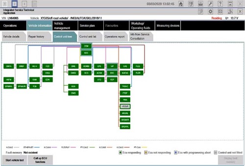
*For the purposes of this section, we will ignore the increasing use of secure gateway modules that effectively block access to a vehicle's systems unless the user obtains a passcode from the vehicle manufacturer. Anyhow, consider the image below-

This image shows one screen from an ISTA (BMW-specific) scan tool, and this view is a major departure from how even manufacturer-specific scan tools used to display information.
What this example shows is a top-down, or bird’s eye view of the topology (layout/configuration) of all the control modules on a BMW vehicle. In addition, in this view, the different colours of the lines that link all the modules each represents a different serial communications network, which makes it a lot easier to form a mental picture of how the vehicle is wired.
Moreover, in this view, the fact that all the modules are rendered in green shows that all the modules are in working condition and that all are communicating over their associated networks as expected. The only exception here is the module rendered in grey; in this case, the “grey-ed out” module is not fitted to the vehicle. Now consider the next image-

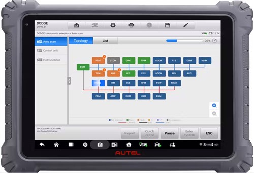
This image shows an example of a new diagnostic tablet manufactured by Autel, one of the leading manufacturers and suppliers of generic scan tools to the aftermarket.
This example shows the same bird’s eye view of the topology of the serial communications systems in a Dodge vehicle, although the colours of the modules in this rendition are somewhat different from those in the ISTA tool. This is a minor point though since the Autel tool (as do all tools made by other manufacturers) comes with a legend that explains what the different colours mean.
There are many other examples of how even generic scan tools made by a variety of manufacturers now present information. However, the single biggest advantage of new scan tools over their older brethren is the fact that a user can now navigate to any module or communications network shown on screens like these directly from this screen, without having to guess which module(s) and/or systems is/are not communicating.
Moreover, by following prompts, a user can navigate directly to a series of colour-coded and interactive wiring diagrams, guided tests, pin-out charts, suggested repair tips, and in some cases, even to online technical support centres and curated collections of TSBs, provided a stable internet connection is available.
Overall, these and other innovations in scan tool functionality represent a sea-change in how we approach modern diagnostics, and therefore, nobody should have reservations about using scan tools to tackle even complex and tricky issues. As a practical matter, modern scan tools have removed a lot of the guesswork from diagnostics, and while we still need all of the traditional skills, like an ability to think critically and ask logical questions, formulating a suitable diagnostic strategy is now easier than it has ever been in the past, which leaves us with this-
Sadly, the implementation of the Competition and Consumer Amendment (Motor Vehicle Service and Repair Information Sharing Scheme) Act 2021 will not turn all of us into expert diagnosticians overnight. However, what does count in our favour is that all major manufacturers of generic scan tools now offer diagnostic equipment with the same capabilities and functionalities as OEM-level tools.
So, even though we will shortly be expected to work on vehicles and systems that we have not seen in the independent repair industry before, doing so will be a lot easier for many of us if we are more comfortable with the tools we will be required to use to diagnose, service, and repair vehicles that are still under warranty.