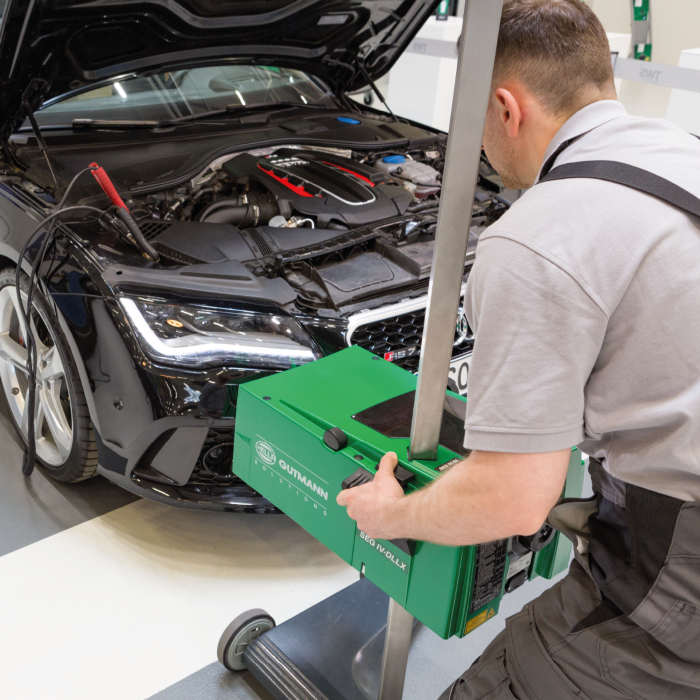
Today, more and more vehicles are equipped with complex headlight technology and lighting assistance systems such as adaptive high-beam assist. With these constantly evolving systems, the challenges faced by workshops in testing and adjusting headlights have also increased. Correctly adjusted and aligned headlights are essential for the safety of all road users. In this article, we look at how to correctly test headlamp performance and ensure they are aimed correctly.
Since asymmetric light distribution appeared on the market in 1957, there have also been statutory provisions for headlamp adjustment.
Headlamps were first aimed at the so-called "10-meter wall". Meaning a vehicle is driven to a distance of 10m in front of a light-coloured wall which had certain markings on it. The headlamps were then checked or adjusted based on these markings.
This has remained the statutory test method today. Still used particularly for checking agricultural or special vehicles. One of the disadvantages of this method is that a relatively large, light-coloured and free wall needed a corresponding amount of space; both not often present in workshops. These factors were ultimately responsible for the development of beamsetters. Such devices enable quicker and more flexible checking of light distribution.
Beamsetters fundamentally simulate the 10 m wall. The lens installed in the beamsetter box shortens the prescribed 10 m distance to 50 cm. A beamsetter can also be flexibly used at different places within the workshop, provided the workshop floor adheres to the required tolerances.
1. PREPARING THE VEHICLE
The composition and condition of the floor are of primary importance to enable exact headlamp adjustment. That is why it also has its own standard (DIN ISO 10604) in which the "test surface" is specified precisely and the permissible tolerances listed. If these tolerances are not adhered to, even minor deviations have a large impact on the light distribution.
Not only are the floor conditions important, but the vehicle must also be prepared for the test by following the below points:
2. SETTING UP THE BEAMSETTER
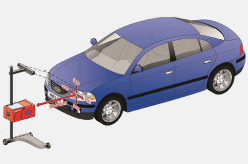
The beamsetter is moved in front of the headlamp to be checked. The beamsetter must be aligned to the middle of the headlamp or to the light source. Vertical and horizontal deviations may not exceed 3 cm. The distance between the beamsetter and the headlamp varies depending on the manufacturer. For the Hella Gutmann beamsetter, the distance between the front edge of the beamsetter and the headlamp may be between 30 and 70 cm (see image).
The beamsetter is then aligned to the vehicle. Beamsetters with a wheel-mounted base must be individually aligned for each headlamp to be checked. For beamsetter devices on rails, the beamsetter needs only to be aligned once. Using the broad-band, laser, or mirror sight, align the beamsetter in such a way that the sight line touches two points situated at the same height, symmetrically to the vehicle’s longitudinal axis.
3. SETTING THE FORWARD INCLINATION OF THE CUT-OFF LINE
Finally, set the "forward inclination" on the device. This corresponds to the tilt angle of the headlamp cut-off line. The forward inclination is given in % and can normally be found on the headlamp. For example, 1% means that the low beam is at an angle of 10 cm at a range of 10 m. The aiming screen is set to the correct percentage using the scaled wheel.
4. CHECKING THE HEADLAMP ADJUSTMENT – SETTING THE LIGHT DISTRIBUTION:
The device now has an optimal setting and the different light distributions can be checked and corrected if necessary.
Switch on low beam:
The cut-off line must run as horizontally as possible along the dividing line over the whole width of the screen. Correct the headlamp adjustment if necessary using adjusting screws. In the case of headlamps with asymmetrical low beam, the cut-off line must touch the dividing line on the test surface. The kink point between the left and right sloping part of the cut-off line must run vertically through the central marking
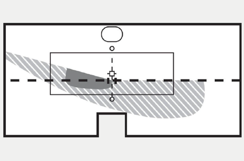
Image 2: The cut-off line must run as horizontally as possible, plus the kink point must run vertically through the central marking.
Switch on high beam:
The light beam centre of the high beam must lie on the central marking (image 3); correct if necessary with the adjusting screws.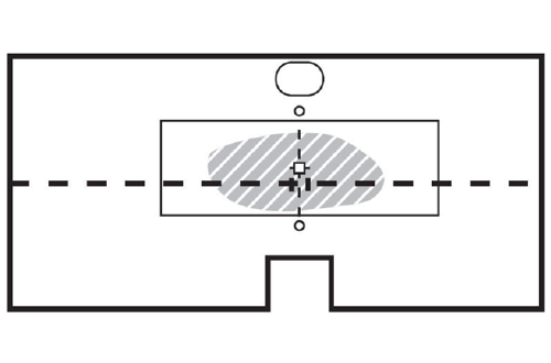
Image 3: The light beam centre of the high beam must lie on the central marking.
NOTE: If the same adjustability is used for both the high beam and low beam headlamps, recheck the low beam.
Some manufacturers have also been offering "high-beam assistants" for some time now as an optional feature. A camera installed in the windscreen recognises when a vehicle is approaching or driving in front of the vehicle and automatically switches the high beam to low. In addition, there is also the so-called "glare-free high beam cut-off line". This high beam system produces a very special light distribution on the road. In contrast to a normal high beam that is displayed on the aiming screen as an oval spot of light, the shape of the glare-free high beam cut-off line tends to be square (image 4).
In order to adjust this high beam function, a menu needs to be called up using a diagnostic tester. The headlamps are moved into a certain position and the glare-free high beam cut-off line is activated. Now the vertical line of the light distribution (as indicated by an orange circle – image 4) must be adjusted exactly to the central marking of the aiming screen. In the case of the glare-free high beam cut-off line, correct adjustment is absolutely essential as otherwise other road users may be exposed to extreme glare.
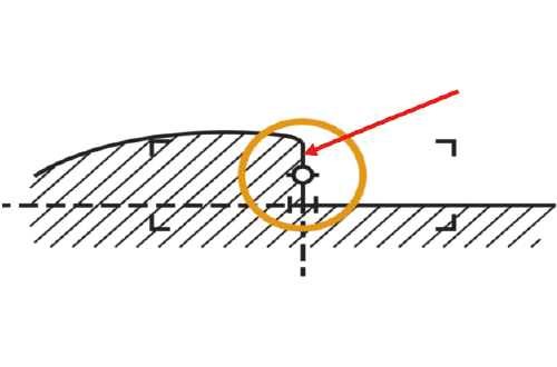
Image 4: The shape of the glare-free high beam cut-off line tends to be square.
For more information regarding headlight adjustment including fog lights view this HELLA Techworld article.
For a no obligation discussion with one of our ADAS calibration specialists, call 1800 061 729 or email [email protected]
This article is brought to you by Hella Gutmann