In Part 1 of this series of articles, we looked at some of the basic operating principles of piston rings on modern engines. We also made the point that some compromises between the design of piston rings and some desired outcomes often result in excessive oil consumption on new engines.
In Part 2, we will discuss some specific issues and problems with modern piston ring designs that contribute, and sometimes, directly cause new engines to burn copious amounts of oil. Let us start at the beginning, which is-
This process is also known as “breaking-in” or “ring seating”, and it is critically important that the vehicle manufacturer’s recommended steps be followed exactly to ensure that the piston rings a) conform to the shape of the cylinders, and b), that the ring faces take on their intended shapes as soon as possible without causing undue amounts of wear on the cylinder walls.
Consider the image below-
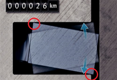
Image source:https://www.ms-motorservice.com.tr/fileadmin/media/MAM/PDF_Assets/Piston-Rings-for-Combustion-Engines_53094.pdf
Although the dimensions, angles, clearances, and range of movement shown in this image are greatly exaggerated for clarity, this image (and the one following) illustrates the changes that occur to a ring face during the running-in process. Let us look at this process in some detail-
At this low mileage, the ring face touching the cylinder wall is still squared-off, and the contact area between the ring face and the cylinder wall is as big as the ring is high when the engine is not running. When the engine is running, however, inertial and frictional forces cause the ring to “twist” in the groove.
In practice, the amount of twist in alternate directions as the piston changes direction is dictated by a) the piston/cylinder wall clearance, b) the ring groove clearance, and c), the ring height, but in all cases, only the top and bottom corners of the ring face are in alternate contact with the cylinder wall as the ring twists in opposite directions.
Thus, since only the corners of the ring’s face are available to form a seal between the ring and the cylinder wall, the sealing of both oil and gas is relatively poor. Therefore, to improve sealing during this stage of the running-in process, ring groove clearances are calculated to allow the inside and outside edges of the ring to touch the edges of the ring groove as the ring twists. In this example, these touch points that act as additional sealing surfaces, are circled in red and assuming that the groove clearance is adequate, these points act as both oil and gas seals to improve the overall sealing ability of the ring.
Note, though, that ring grove clearances are also required to allow the ring to rotate in the ring groove, and both radial and axial movements of the ring (in the ring groove) are intended to allow the ring face to wear down to an ideal shape within a few thousand kilometres of use.
Now consider the image below-
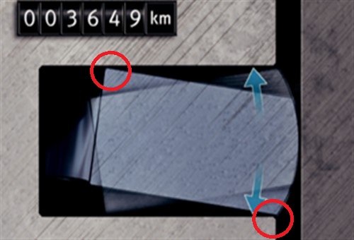
Image source: https://www.ms-motorservice.com.tr/fileadmin/media/MAM/PDF_Assets/Piston-Rings-for-Combustion-Engines_53094.pdf
In this image, the ring face is shown having worn down to an ideal convex shape, This represents the ideal shape because the smaller contact area between the ring face and the cylinder wall translates into reduced friction between the ring face and the cylinder wall and improved gas sealing, which begs the question of-
What can go wrong?
If we assume a perfect engine design, in the sense that-
…we would have an engine in which the piston rings form almost perfect gas and oil seals. We would also have an engine in which the piston rings in all cylinders wear evenly and at a predictable rate, and, therefore, we would have an engine that would last (almost) forever.
The truth is, however, that perfect engines do not exist. Moreover, in this age of built-in obsolescence, no car manufacturer is ever going to maximize even crucial components like piston rings for both performance and longevity, simply because there is no money to be made from such components.
So what does this mean for excessive oil consumption on new engines? We can summarise this issue in table form, so consider the table below-
|
Ring requirement |
Friction |
Running-in |
Durability |
|
High ring tension |
Poor |
Good |
Poor |
|
Low ring tension |
Good |
Neutral |
Good |
|
High wear resistance |
Undetermined |
Poor |
Good |
|
Low wear resistance |
Undetermined |
Good |
Poor |
|
Low ring height |
Good |
Neutral |
Good |
|
High ring height |
Poor |
Good |
Poor |
This table is based on the assessments a piston ring manufacturer with a global reach had made on hundreds of thousands of worn piston ring/cylinder combinations on engines of all types, designs, and capacities. Nonetheless, to understand the findings of this study, these results must be judged against the background of the minimum characteristics piston rings are required to have. We have reproduced those requirements here from Part 1-
Based on the stated required characteristics and observed test results, we can look at the effect of reduced ring heights on oil consumption, since reducing ring heights have become somewhat of a trend in new engine designs. Consider the image below-
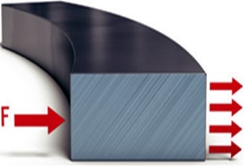
Image source: https://www.ms-motorservice.com.tr/fileadmin/media/MAM/PDF_Assets/Piston-Rings-for-Combustion-Engines_53094.pdf
In this image, the rectangle represents a piston ring in cross-section, while the red arrows represent the forces acting on the ring when the engine is running. While we do not have to assign specific values to these arrows, arrow “F” represents the total force* acting on the ring, while the four smaller arrows represent the total contact pressure the ring face exerts on the cylinder wall.
*In this case, the total force consists of the rings’ inherent spring tension, and the effect of combustion pressure acting on the back of the ring.
Based on the table above, we see that a high ring height has a large contact area, which produces high friction values, which translates into high rates of wear. On the upside though, high rings running-in relatively quickly.
Thus, in terms of modern trends in engine design, high rings are undesirable because they produce lots of friction, which requires lots of fuel to overcome. High rings also wear out relatively quickly, which is bad from a marketing perspective.
Now consider the image below-
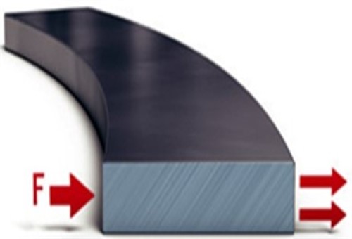
Image source: https://www.ms-motorservice.com.tr/fileadmin/media/MAM/PDF_Assets/Piston-Rings-for-Combustion-Engines_53094.pdf
This image also represents a piston ring and the forces acting on it, but in this example, the ring height had been reduced by 50 per cent, which is a common reduction value in many modern engines to reduce frictional losses by reducing the rings' contact area with the cylinder walls.
In practice, the contact pressure between a ring face and the cylinder wall when the engine is running is a function of-
Therefore, if an engine designer needs to reduce the amount of friction between the ring and the cylinder wall by 50 per cent, the designer can reduce the ring's height by half. However, while doing this will reduce the active contact area by half, the ring's spring tension needs to be doubled to maintain the required contact pressure between the ring face and the cylinder wall.
In practice, reducing ring heights do in fact, produce measurable reductions in frictional losses. However, the problem with this approach is that smaller contact areas also reduce the smaller contact area’s ability to provide an effective seal not only against both gas blow-by but also in terms of preventing oil from seeping past the ring into the combustion chamber during the running-in process.
While most manufacturers now use flatter rings whose faces are coated with a variety of metals and other substances to improve sealing, there are no real, objective methods to predict how a ring with a low height will react to heat, pressure, and rapid changes in the direction of movement in an engine that is operated under real-world driving conditions. In short, engine designers have no way to make absolute, or even halfway accurate predictions on how piston rings with low heights will behave under real-world operating conditions.
More to the point, while computer modelling can generate estimated values for things like ring flutter, ring twist, ring rotation, and other parameters, engine designers cannot observe these movements and effects in real-time as they happen during engine operation. Therefore, poor ring performance caused by things like excessive ring flutter at the ring gap, excessive ring twisting caused by premature or excessive ring groove wear, and the long-term effects of boundary lubrication conditions at the top and botom of the cylinders very often only becomes apparent to engineers when they strip an engine tear down to assess wear patterns.
If engine designers could observe ring bahaviour in real time, they would likely be able to design rings that outperform the rings we see on many engines today. However, as things stand now, discovering that rings perform poorly often comes very late in an engines’ design/development phase, meaning that fixing the problem might be prohibitively expensive.
These inspections/assessments are, in fact, the only way engine designers have to gauge the performance of the coatings on ring faces, which if they are successful, can greatly reduce ring wear rates. However, while the primary function of ring face coatings is to reduce face wear, the fact is that not all coatings reduce the amount of ring wear during the running-in phase to the same degree.
Moreover, the practical effect of this initial wear is that once it starts, it continues, which means that the surface area presented by compression rings that are just over 1mm, or sometimes less than 1mm thick, is continually reduced as the (original) flat face of the ring wears down to assume a progressively more convex shape.
Observant readers will no doubt have noticed that the table we presented at the top of this section does not mention the effects of undesirable ring characteristics on oil consumption. However, it does not have to, because simple logic and real-world observations by thousands of mechanics the world over have made it abundantly clear that oil consumption rates on new engines have increased almost in direct proportion to the progressive reduction in ring heights, which progressively reduced piston rings' contact with cylinder walls.
This point brings us to perhaps the most important characteristic pistons rings should have, but which many do not (or not in sufficient measure) this characteristic being-
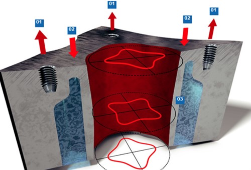
Image source: https://www.ms-motorservice.com.tr/fileadmin/media/MAM/PDF_Assets/Piston-Rings-for-Combustion-Engines_53094.pdf
While it might seem that all cylinders on all engines are perfectly cylindrical, this is very frequently not the case and the above image shows the types of deviations from cylindrical that are present on a large percentage of new engine designs- albeit in varying degrees. Note, though, that a) the distortions showed here are greatly exaggerated for clarity, and b) that the severity of these types of distortions varies between engine types and designs.
Let's look at what the numbered labels and the directions of their associated arrows in this image mean-
1) The upward force of the cylinder head bolts
2) The downward and opposite force of the head gasket pushing against the cylinder block
3) Cylinder deformation as the result of the opposing forces
In this example, the red clover-like shapes define to direction of deviations from round. Note that the pattern of deformation in the middle of the cylinder is oriented 90 degrees away from the deformation patterns at the top and bottom of the cylinder- which makes it even more difficult for piston rings to continually adapt to the cylinder's shape.
At this point, it might be instructive to point out that deformed cylinders are not exactly a new development: they have, in fact, always been a feature of internal combustion engines ever since they were invented although, in the ancient days, cylinder deformations were almost always the result of poor machining.
However, before the advent of exhaust emission regulations, engine designers paid scant attention to things like fuel efficiency, excessive oil consumption, and reduced engine life, all of which are undesirable traits in modern engines.
Moreover, thirty years and more ago, it was easy to "fix" excessive oil consumption by using piston rings that were 3mm thick, and sometimes, more than 3 mm thick. Put simply, this remedy was possible because nobody cared very much (if at all) about the fact that overcoming the additional friction required the use of more fuel.
So what has changed since then? Sadly, a lack of space precludes a comprehensive discussion of all the important changes in engine design over the past several decades, but there is no doubt that the introduction of legally enforceable exhaust emission regulations had been the principal driving force behind improved engine designs.
Apart from introducing fuel injection to reduce fuel consumption, other design innovations included improved engine casting and machining methods, reduced piston and crankshaft weights. Perhaps most importantly, though, the development of advanced lubricants to greatly reduce frictional losses was arguably the single biggest innovation that made improved engines possible.
However, efforts to reduce the overall weight of engines have now reached the point where the balance between the strength and rigidity of an engine block casting depends more on a casting mould's design than it does on the amount of material used in the casting. Put differently, this means that in some cases, and especially on aluminium engines, the finished block is not quite as rigid as it might have been, meaning that many aluminium engine blocks are distorted simply by bolting down the cylinder head(s) during assembly in the factory.
The schematic at the top of this section shows the effects of simply tightening the cylinder head bolts on an aluminium engine block. To be sure, while these kinds of deformations are measured in hundredths of a millimetre, synthetic oil formulations now allow piston/cylinder wall clearances of as small as 0.0127mm*. Therefore, it should be obvious that distortions of even a few hundredths of a millimetre might already be too much on some engines.
* This value applies to hypereutectic pistons, which are pistons that have a silicon content of up to 20 per cent to stabilize and control their expansion rate(s).
Consider the image below-
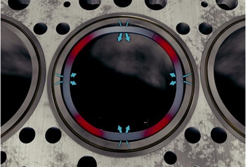
Image source: https://www.ms-motorservice.com.tr/fileadmin/media/MAM/PDF_Assets/Piston-Rings-for-Combustion-Engines_53094.pdf
This image shows an example of a cylinder with Stage 4 deformations*, which are caused simply by torquing cylinder head bolts to their recommended values.
* We will discuss other stages of cylinder deformations in a follow-up article.
Although the distortions in this example are greatly exaggerated for clarity, the exaggerations illustrate the effects such distortions can have on piston rings. In this case, the distortion pattern has created four leak paths through which combustion gasses can pass into the crankcase and through which oil can pass into the combustion chamber.
Except for a few experimental designs, piston rings are neither designed to, nor capable of sealing cylinders on which this type of deformation is present. Nonetheless, engine designers and manufacturers have found that by reducing the thickness of compression rings to one millimetre or less, they can make compression rings that will (sometimes) adapt to Stage 4 deformations for a limited time.
Put differently, this means that rings can sometimes be made "fluid" enough to adapt to complex deformations in cylinders, albeit for a limited period. While this period varies between engines, the rings' "fluid" period ends when boundary lubrication conditions at the four points shown here a), wears away the rings at these points, and wears "holes" in the cylinder walls at the same points, at the same time.
This largely happens because Stage 4 deformations prevent the rings from rotating in their grooves, with ring rotation being one of the principal mechanisms that ensure even wear of piston rings, piston ring grooves, and cylinder walls, which leaves us with-
Although “built-in” cylinder deformations are fairly common on engines with aluminium engine blocks, some aluminium engines are affected more than others. Moreover, these kinds of defects are not confined to aluminium engines. They also occur on engines with cast iron engine blocks, albeit less often than on aluminium engines, and often not to the same degree.
As a result, some ring failure modes often occur on some engines, and seldom, or, less often than on some other engine designs. Thus, in the next article in this series, we will discuss specific piston ring failure modes and their causes.