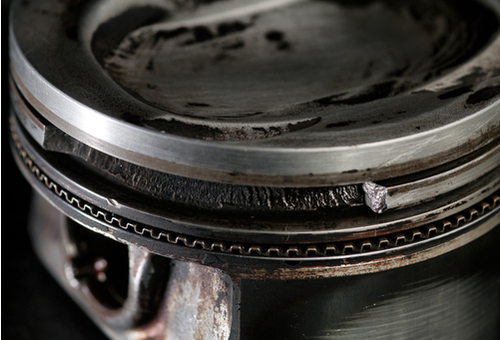
We concluded the previous article in this series by mentioning cylinder bore defects as a contributing cause of excessive oil consumption, and in this article, we continue the discussion of cylinder bore defects in new engines. Let us start with-
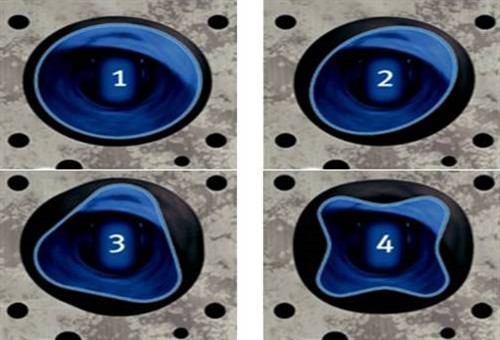
Image source: https://www.ms-motorservice.com.tr/fileadmin/media/MAM/PDF_Assets/Piston-Rings-for-Combustion-Engines_53094.pdf
This image shows examples of the most common cylinder bore defects that exist even on new engines, but before we get to specifics, we need to state that there are no “perfect” piston ring designs. All piston ring designs are the result of compromises between many needs, requirements, and demands. These include (among many others) specifics like-
In practice, these tasks would be relatively easy to accomplish if a) all cylinder bores were always perfect cylinders, b) if engine blocks, pistons, and piston rings were thermally stable, and c) if some of the above (bullet) points were not simultaneously complementary and contradictory. For instance, a precisely defined oil film is required between the cylinder wall and all piston ring faces to limit the mechanical wear of cylinder walls. At the same time, however, the oil film tends to lift the compression rings' aces off the cylinder wall under some conditions, which reduces the compression rings’ gas sealing ability.
There are many other examples of competing requirements and/or demands, the effects of which are greatly increased when cylinder bores are not cylindrical. Let us look at these defects, which are more properly known as "stages of deformity", as shown in the panel of images above, in some detail-
Stage 1
This stage represents the ideal; the cylinder bore is perfectly circular, and the cylinder bore has the same diameter throughout the length of the cylinder. Note, however, that the ideal shape is often different from the actual shape of the cylinder bore, particularly in the axial direction caused by poor machining during the engine manufacturing process.
Put differently, this means that on a great many new engines, the cylinder bores are tapered in one direction, and often, not to the same degree.
Stage 2
While oval cylinder bores are often the result of poor machining practices during the manufacturing process, these kinds of faults are more commonly the result of uneven heat dissipation caused by poorly designed and/or poorly functioning engine coolant circulation patterns.
Put differently, this means that if the rate of coolant flow is not equal on all sides of the cylinder, the temperature differences can, and often does, cause some parts of the engine to expand more (or less) than other parts. Uneven heat dissipation in its turn causes cylinder walls not only to wear unevenly but also to wear at accelerated rates.
Note that another leading cause of Stage 2 deformations involves the different thermal properties of engines that have cast iron blocks and aluminium cylinder heads. Since the two metals expand and contract at different rates, cylinder bores are forced into irregular shapes as a result.
Stage 3
Triangular wear patterns such as this are, for the most part, the combined result of uneven heat dissipation and distortions caused by cylinder head bolt tightening. Note that Stage 4 distortions can (and do) occur even if the head bolts are tightened in the correct order and to specified torque values. (Refer to Part 2 of this series of articles for more details).
Stage 4
As mentioned elsewhere, this pattern of deformation is caused by the opposing mechanical forces that result from tightening cylinder head bolts. Refer to Part 2 of this series of articles for more details.
Given that compression ring heights are now about 1 mm (or less), modern compression rings have a significantly lower spring tension to reduce the pressure the ring faces exert on the cylinder walls. Thus, the combination of lower surface contact area and a lower contact pressure reduces cylinder wear, but reduces sealing ability, at the same time.
Therefore, modern compression rings only work well when they are mated to cylinders that are as close to perfectly cylindrical as modern mass-production methods can make them. However, cylinders are rarely perfectly cylindrical from top to bottom under normal operating conditions, but to compensate for deviations that are smaller than about three-hundredths of a millimetre, the fluidity built into the design of thinner compression rings translate into satisfactory ring performance.
Consider the image below of a cylinder at engine operating temperature, in which no Stage 2, 3, and 4 deformations are present. Note though that the degree of expansion at the top is exaggerated for clarity-
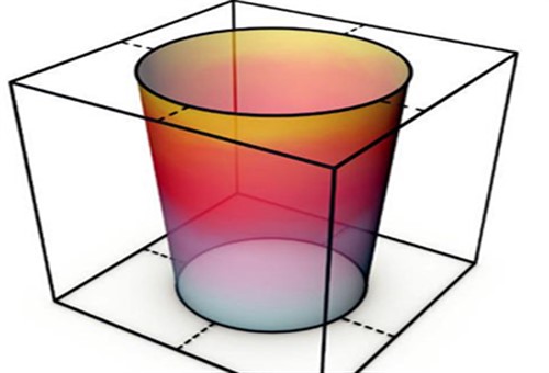
Image source: https://www.ms-motorservice.com.tr/fileadmin/media/MAM/PDF_Assets/Piston-Rings-for-Combustion-Engines_53094.pdf
In this example, the cylinder deforms into a “funnel”-like shape, with the top of the cylinder having a bigger diameter than the bottom. Just how big this difference gets depends on many factors, including the engine design, bore diameter when the engine is at ambient temperature, and the engine's typical operating temperature, but we can illustrate one example without actually doing the math by assuming the following-
We can skip over many steps in this calculation from this point onwards, but these values yield a result of 0.57mm, which means that if the rings were to maintain their specified ring joint gaps, the rings have to increase their lengths by 0.57mm to maintain proper contact pressure on the cylinder walls to ensure efficient gas and oil sealing. As we mentioned elsewhere, this is relatively easy to accomplish when cylinders are free of Stage 2, 3, and 4 deformations.
However, no commercially available piston rings have anywhere near enough fluidity to compensate for Stage 2, 3, and 4 deformations- even in cases where these deformations are smaller than about three-hundredths of a millimetre. Thus, when poor ring fluidity and cylinder deformations that exceed about two to three-hundredths of a millimetre are combined, the following result is almost inevitable-
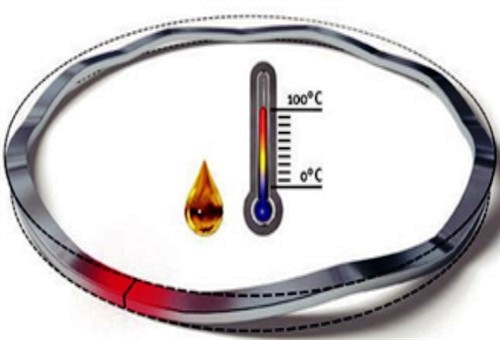
Image source: https://www.ms-motorservice.com.tr/fileadmin/media/MAM/PDF_Assets/Piston-Rings-for-Combustion-Engines_53094.pdf
This image shows an example of what typically happens when a piston ring's thermal expansion and excessive cylinder deformations affect a ring to the point where the joint gap can no longer accommodate the rings' expansion and the cylinder deformations.
Note the area in red; this is where the ring ends meet, which prevents further expansion of the ring. If more pressure in the form of heat and/or dynamic cylinder deformations is placed on the ring, the ring can only deform as shown here. If it happens, the ring can become jammed into its groove, which would prevent the ring from performing one of its most critical functions, this function being-
Contrary to popular belief, piston rings perform three kinds of movements during engine operation. These movements are critical in the sense that if they do not occur, piston rings can neither dissipate heat nor form effective gas and oil seals. The results of these failures include-
With the above in mind, let us look at the three kinds of movements piston rings perform, starting with-
Rotation
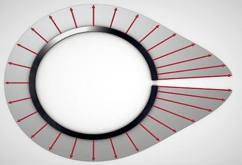
Image source: https://www.ms-motorservice.com.tr/fileadmin/media/MAM/PDF_Assets/Piston-Rings-for-Combustion-Engines_53094.pdf
Although the oil control rings in both 2-stroke and 4-stroke engines exert equal pressure on the cylinder walls in all directions, the pressure distribution pattern of compression rings in 4 stroke engines is asymmetrical, as shown here. This pressure distribution pattern is important for two reasons: the first being that the increased outward pressure at the ring gap reduces ring flutter. The second reason is that if compression rings did not rotate in their grooves, the increased pressure at the ring gap ends would cause uneven wear of the cylinder walls.
As a practical matter though, the rotation of rings in their grooves increase both gas and oil sealing because the ring's rotation distributes a film of oil between the bottom of the ring and the bottom of the piston groove. Moreover, since the pressure distribution patterns of compression rings are unequal, the rotation of compression rings prevents uneven wear of both the rings and the cylinder walls.
As a rule of thumb, compression rings typically rotate between five, and about fifteen times per minute depending on the engine speed, the bore diameter, and the height(s) of the rings. Regardless of the rings' rate of rotation, though, all rotating movements are caused by a) the crosshatch (honing) angle, with steeper honing angles producing higher rates of rotation than shallower angles, and b) the rocking motion of the piston at TDC and BDC.
Note, though, that rotation of the rings only occurs predictably in cylinders that are not significantly deformed. In this context, "significantly deformed" means a) cylinders free of Stage 3 and 4 deformations and b) that Stage 2 deformations are not greater than about 4-hundredths of a millimetre.
Axial movements
As mentioned above, the underside of compression rings should ideally be in contact with the bottom of the ring grooves over the whole width of the rings to improve oil and gas sealing through the oil film between the two surfaces. However, at moderate to high engine speeds, the rings are subjected to high inertial forces that lift the rings away from the ring groove surfaces. This movement reduces the damping action of the oil film between the ring and the ring groove surfaces.
While this particular sealing action is usually efficient on engines on which the rings had been run in properly, poor running in practices can (and often do) cause accelerated wear of the ring grooves. If this happens, the enlarged clearance between the rings and the groove surfaces collect excessive amounts of oil, which is then sucked into the combustion chambers by the negative pressure in the cylinders during the intake stroke.
An additional effect of poor running in practices is that the enlarged ring/groove clearance increases the amount of ring flutter that occurs. Ring flutter happens when a ring starts to "bounce" in its groove at high frequencies, which destroys its sealing ability. As a point of interest, it is worth noting that ring flutter always starts at the ring gap ends and spreads outward around the rings' circumference, with fluttering motions' amplitude increasing toward the point directly opposite the ring gap.
Radial movements
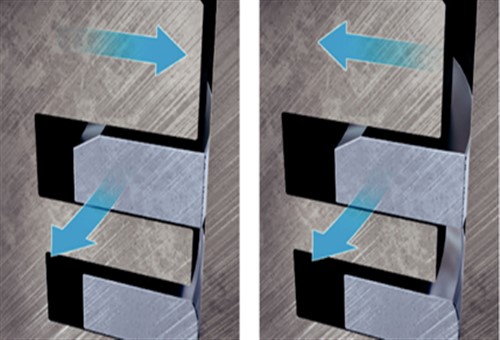
Image source: https://www.ms-motorservice.com.tr/fileadmin/media/MAM/PDF_Assets/Piston-Rings-for-Combustion-Engines_53094.pdf
It would be reasonable to assume that pistons move straight up and down in the cylinders. However, pistons perform small, but measurable rocking motions at both TDC and BDC because the changes in the direction of travel transfer the weight of the piston crown from one side of the cylinder bore to the opposite side.
As shown here, the effect of the rocking motion is to "squeeze" the rings into their grooves on one side of the piston and to allow the rings on the opposite side of the piston to “slide” out of their grooves. Although the primary purpose of this movement is to continually scrape off and remove carbon deposits from the ring grooves, this motion also helps to maintain the oil film between the rings and the bottom surfaces of the ring grooves, which brings us to-
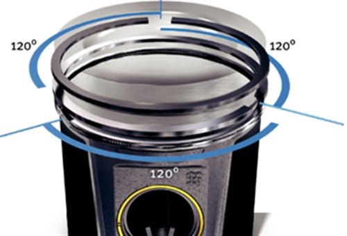
Image source: https://www.ms-motorservice.com.tr/fileadmin/media/MAM/PDF_Assets/Piston-Rings-for-Combustion-Engines_53094.pdf
Elsewhere in this article, we used an example of a piston ring with a diameter of 100mm, which ring has to expand by as much as 0.57mm to maintain sufficient surface pressure for it to function as a gas and oil seal. If, for the purpose of this article, we assume -
…then the rings in that engine will provide adequate sealing against gas blow-by and satisfactory protection against excessive oil consumption.
However, as new engines go, we often assume too much. For instance, many new engine blocks are severely affected by Stage 3 and 4 deformations, which in many cases negate the purpose of the ring gaps, which is to allow rings to a) expand and b) to allow rings to expand without hampering their various movements in their grooves.
So what does this have to do with ring gap spacing? Simply this; when new engines are assembled, the ring gaps are spaced 120 degrees apart to create a labyrinth seal that makes it more difficult for combustion gas and oil to escape past the rings during an engine's first few minutes of operation.
In a perfect piston/ring combination, the maximum permissible amount of blow-by gas at first start-up is around 0.5 per cent of the volume of the intake air. Although this value varies somewhat between engine designs and capacities, the basic calculation in all cases involves the ring gap in the rings’ installed state and 50 per cent of the clearance between the piston skirt and the cylinder walls.
Nonetheless, we do not need to delve into the intricacies of calculating the permissible volume of blow-by gas for any given engine here, beyond saying that with a perfect piston/ring combination the amount of blow-by gas will get progressively smaller as the rings wear in. Of course, this implies that even if an engine burns a bit too much oil when it is new, it will consume progressively less oil as the rings run in.
However, we often see the opposite effect as rings on new engines are run in. Instead of using progressively less oil after a few thousand kilometres of use, many new engines begin to burn progressively more oil after a few thousand kilometres of use as the result of various, but common causes.
Lack of space precludes a discussion of even the most common causes of this phenomenon here, but we can say that because piston rings rotate in their grooves when a cylinder bore is not significantly deformed, the ring gaps “overtake” each other as the rings rotate at different rates. Therefore, the ring gaps can be in an almost infinite range of relationships with respect to each other, but only if all the rings on a given piston are free to rotate in their grooves.
Thus, the ring gaps on compression rings could sometimes be aligned exactly, which momentarily doubles the area through which combustion gas can pass into the crankcase, and oil can pass into the combustion chamber. In most cases, though, the rings will continue to rotate, thereby taking the gaps out of alignment, but in some cases, and for various reasons, the rings can become stuck while their gaps are aligned, which brings to-
In the next article, we will discuss some of the reasons why rings become stuck with their gaps in alignment, as well as some specific piston ring failures and their causes.
