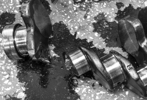
All failures of major components on motor vehicle engines, such as the catastrophic crankshaft failure shown above, can be explained in one way or another, although in the case of crankshaft failures, the cause may not always be immediately apparent. Nonetheless, to understand failures of this kind, we need to understand that crankshafts are not as rigid as we may think, and in many cases, crankshafts fail because they literally vibrate themselves to pieces. Thus, in this article, we will take at a closer look at how and why crankshafts vibrate under load, and how the resulting vibrations and oscillations are damped out with torsional vibration dampers, starting with this question-
Known by many different names such as harmonic balancer, harmonic damper, crank pulley, power pulley, and many others (all of which are technically incorrect to varying degrees), a torsional vibration damper is the large and massive device on the front end of the crankshaft and whose purpose it is to, “cancel out third harmonic distortion by using intermodulation between the second harmonic and the fundamental in the space charge regions of the triodes.” [Italics added for emphasis]
This is quite a mouthful, but fortunately, we do not have to delve too deeply into the physics of vibration damping. Suffice to say that what we commonly refer to as the “crank pulley” on an engine, is in fact a vibration-damping device that is specifically tuned to each engine/crankshaft combinations’ particular natural vibration frequency. Commonly made from cast iron because of cast iron’s high specific gravity, each vibration damper is designed to absorb the specific range of vibrational frequencies that is unique to each engine type and design. In fact, the term “harmonic balancer” derives from the fact that some manufacturers use the hub of the damper to cancel out some engine vibrations simply by adding or removing mass from the hub, which, incidentally, has nothing to do with damping out crankshaft vibrations.
In practice, a vibration damper consists of a hub and an inertia ring with a cushion of pliable rubber between them, with the rubber absorbing the crankshafts’ vibration by flexing between the hub and the inertia ring. Since this continual flexing produces heat, the conversion of vibration into heat is the actual mechanism that damps out potentially destructive vibrations and torque induced deformations of the crankshaft, which begs this question-
All objects vibrate when another object strikes them, with a bronze bell being a good example. However, the frequency at which the bell vibrates is dictated by the bells’ mass, its overall shape, and how hard it is struck, which is why no two seemingly similar bells ring out at the same frequency, even if they are struck with equal force by the same object.
Although automotive crankshafts can in some ways be thought of as a series of bells that are connected through the crank webs, the mechanisms that produce vibrations in a crankshaft are a little different from those that produce a ringing sound from a bell. The most important of these factors is the fact that despite their enormous structural strength and rigidity, no crankshaft is 100% rigid, which means that all crankshafts flex and deform when off-centre forces are applied to them.
In this context, an off-centre force would be the torque produced during combustion; in this case, torque being equal to the force exerted by the combustion pressure, multiplied by the distance of the offset between the main bearing centre line and the centre line of the bearing journal. For the moment though, we will ignore the effects of the crankshaft’s inertia, changing dynamic clearances, as well as the flywheels’/torque converters’ mass and inertia. So here is what happens when a cylinder fires while the engine is under load; consider the image below-
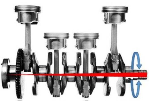
In this image, the tapering red line across the centreline of the crankshaft represents torque-induced deformations of the crankshaft, while the blue arrows represent the back-and-forth oscillations that occur as the deformations are absorbed by the crankshaft. Note however that the red line widens towards the front of the engine, which represents the fact that the amplitude of torque-induced deformations increases progressively towards the front of the crankshaft.
When a piston exerts a downward force, it only does so for about 100 degrees of crankshaft rotation, but some of that force is lost as a result of the crankshaft flexing, since all crankshafts are inherently flexible. Soon after 100 degrees of rotation, the crankshaft attempts to return to its neutral state, but in snapping back it overshoots its neutral position, and as a result, it deforms in the opposite direction. This sets up an oscillation that may or may not be damped out, depending on the length of the crankshaft, the diameter of the main bearings and journals, engine speed, firing order of the pistons, changing dynamic clearances, and of course, the energy of the initial downward force.
Nonetheless, and more to the point, the amplitude of the oscillation varies based on the position of the piston that produced the oscillation. For instance, if the oscillation was produced by the piston closest to the flywheel/torque converter, the initial deformation and subsequent oscillation is very small, since the mass and inertia of the rapidly spinning mass is a reasonably effective vibration damper.
However, the further away from the flywheel/torque converter a piston is, the greater the initial deformation and resulting oscillation becomes, because some of the spinning mass’ ability to absorb or resist the initial deformation is absorbed by the length of the crankshaft between the spinning mass and the piston that produced the deformation. Taken together, all the contributing factors mentioned up to this point combine to cause a progressive increase in the amplitude of crankshaft oscillations towards the front of the crankshaft, which can reach up to two degrees of crankshaft rotation in opposite directions.
It should be noted though that two degrees of crankshaft rotation is an extreme case. In the vast majority of engines, crankshaft oscillations rarely exceed about one degree, but even so, this is enough to destroy a crankshaft in very short order; unless the torsional vibration damper is effective in stabilizing the crankshaft, that crankshaft has a life expectancy of mere hours before it suffers a fatigue fracture.
While the above should suffice to describe the basics of what causes crankshafts to vibrate, it is necessary to explain some technical terms to understand why any given torsional vibration damper is designed for a specific application, and is therefore NOT interchangeable with any other damper- even if it does fit on an engine it was not designed for. Let us start with-
Frequency
This refers to how many things occur in a specified period, typically expressed as cycles per second, which is in turn, expressed as Hertz (abb HZ). The frequencies at which all crankshafts vibrate naturally are always expressed as Hertz/second, and are constant values that do not vary with engine speed.
Orders
This refers to the total number of events that occur during a single crankshaft revolution, which varies with engine speed. However, note that since orders occur in precisely defined increments relative to each other, orders are sometimes erroneously referred to as harmonics*.
*”Harmonics” refers to multiples of a base frequency based on time, while orders are event based regardless of the time elapsed. Therefore, torsional vibration dampers are tuned to a single frequency, and they therefore damp out the orders of only that frequency in the crankshaft at different engine speeds.
Mode
This describes the deformation patterns in the crankshaft, but more particularly, the number of places in the crankshaft where the twisting moment of the crankshaft changes direction, i.e., from clockwise to counter clockwise.
Node
This describes the points in the crankshaft where deformation is zero, i.e., the point where deformation in one direction stops, and deformation in the opposite direction starts.
Inertia
In this context, inertia is the tendency of any rotating mass to resist changes in its rotational speed. In simple terms, rotational inertia is determined by the relationship between a spinning object’s mass and diameter.
While the above descriptions are very interesting, they all play a role in the design of torsional vibration dampers since they all contribute to a phenomenon known as-
Any given engine will pass through several major critical engine speeds throughout its operating range. However, due to the nature of resonances and harmonics, not all resonances are dangerous or harmful, which is why critical engine speeds are categorised as either major critical engine speeds, or minor critical engine speeds. Here is what each category means-
Major critical engine speeds
Put simply, a critical engine speed (RPM) is one at which torque induced vibrations occur at the same frequency as the crankshaft’s natural vibration frequency. When this occurs, the two frequencies resonate with each other, and if the situation is sustained for long enough, the resonating frequencies may amplify each other until the combined frequency is powerful enough to cause a fatigue failure of the crankshaft.
It should be noted though that while major critical engine speeds can, and do produce crankshaft failures, they can also produce other effects, such as sheared-off crank pulley keys, sheared-off flywheel and clutch pressure plate bolts, excessive and accelerated wear of timing chains, and even damage to manual transmission input shaft bearings and (RWD) differential pinion bearings.
Minor critical engine speeds
At minor critical engine speeds, torque-induced vibrations of the crankshaft may exist at several different frequencies, but instead of amplifying each other, these vibrations cause harmonics that cancel each other out, thus assisting in damping out vibrations.
On the vast majority of vehicles in use today, both the crankshaft and the torsional vibration damper will last the life of the vehicle without causing issues of any kind. However, long experience in the car repair trade has taught this writer that when issues, failures, and problems do occur, the cause can usually be traced back to one or more of the following-
Insufficient cooling
Since a properly functioning damper generates high temperatures, it is critically important that the damper be cooled effectively. For this reason, most cars have slits or vents in splashguards under the engine to allow a sufficient airflow around the lower parts of the engine to cool down the damper. Blocking, or obstructing these vents will therefore almost certainly lead to premature damper failure.
Mechanical damage to the inertia ring
The inertia ring is the outer, grooved part of the damper that carries the serpentine belt. Damage caused by impacts with for instance, road debris deforms the ring, which in turn, places an unequal load on the rubber lining between the inertia ring and the hub of the damper. Over extended periods, such damage can cause the rubber lining to overheat and disintegrate, which in turn, can cause the inertia ring to separate from the hub- usually with dire consequences for the radiator and other parts.
Oil leaks
All engine oil formulations will attack and degrade the rubber lining of the damper if it encounters the rubber lining. Over extended periods, this may bring about a situation similar to the one described above.
Installation errors
The two most common installation errors are driving the damper home on the crankshaft with a hammer, and using the centre bolt to pull the damper onto the nose of the shaft. Both methods can, and do deform the damper, which destroys its ability to damp out crankshaft vibrations because its mass distribution has changed. Always use the methods and tools prescribed by the manufacturer when installing a torsional vibration damper.
Removal errors
On many, if not most engines, it is necessary to remove the damper to change a timing belt, so always use a puller that pulls on the hub of the damper, as opposed to pulling on the inertia ring, which will destroy the rubber lining in the damper. This will in turn, destroy the dampers’ ability to damp out crankshaft vibrations.
Incorrect serpentine belt tension
While automatic tensioning devices are designed to maintain the belt tension at a specified value, these devices wear out over time, as we all know. Thus, at some point, the belt tension may become low enough to cause belt flutter, which places high-frequency cyclical shock loads on the rubber lining in the damper. Depending on the frequency of the cyclical loads, the damper may become unable to damp out crankshaft vibrations, or worse, the cyclical loads may aggravate the crankshaft vibrations to the point where crankshaft failure becomes a distinct possibility.
From the above, it should be obvious that there is vastly more to torsional vibration dampers than meets the eye. Therefore, it is imperative that these devices should only be replaced with OEM equipment to ensure proper operation of the damper.
However, guard against the temptation to fit an SFI-certified unit simply because it is SFI- certified. This certification only means that the unit was rotated at high speed without any torsional inputs whatsoever, and therefore, this certification only means that the unit will not fly apart under centrifugal forces, or that the inertia ring will not separate from the hub if the rubber lining fails.
Essentially, the FSI certification is a safety certification that does not have anything at all to do with the certified unit’s ability to control crankshaft vibrations.
