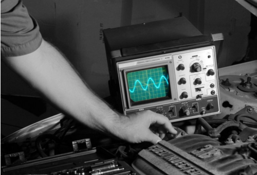
Do you have a diagnostic comfort zone? Do you feel more comfortable diagnosing only certain types of faults or issues, and tend to shy away from attempting to diagnose faults in areas that fall outside of what you know best? There are no penalties for answering “yes” to both questions (many of us do), but here is another question; how willing are you to step out of your comfort zone to learn new skills, such as for instance, learning to use a digital storage oscilloscope to diagnose CAN bus faults, which, admittedly, is not everyone’s cup of tea?
While the complexity of CAN bus systems must not be underestimated, these systems and their issues need not be the exclusive preserve of auto electricians. Thus, in this article, we will take a closer look at CAN bus systems in terms of how they work and what they do, and also share some basic trouble shooting and diagnostic tips, starting with-
Limited space precludes a comprehensive discussion on the various topographies of CAN bus systems, but suffice to say that all CAN bus systems do the same thing, which is to provide serial communications between all the control modules on a vehicle. For instance, the CAN system that controls safety critical communications can transmit input data from the wheel speed sensors via the ABS control unit simultaneously to the ECM (Engine Control Module), TCM (Transmission Control Module), IC (Instrument Cluster), and all components of the (SRS) Supplementary Restraint System) in what amounts to real-time.
In terms of operation, CAN systems transmit data in frames, with each frame consisting of a series of encoded bits of data, each of which represents either “1” or “0”. In practice, bits are the smallest pieces of data that can be transmitted, and therefore, each message is constructed of a series of encoded bits of data. However, to allow for critical messages to enjoy priority over other, less critical messages, data messages are constructed in a manner that subjects all the communications on a particular CAN bus to very strict arbitration rules.
For instance, the first bits after the start of a message are identifiers that identify the transmitting control module; the lower the value of the identifier, the higher the priority of the message becomes. Conversely, the higher the value of the identifier, the lower the priority of the message becomes. This is an important point to bear in mind, since the arbitration scheme’s purpose is to prevent two or more control modules from transmitting data at the same time on the one hand, and to allow safety-critical data to be transmitted ahead of non-safety critical data, on the other. One example of non-safety critical data would be for instance, instructions to the BCM (Body Control Module) to lock the doors above a certain road speed.
The next series of bits in a data message comprise the data payload, which is the actual data being exchanged between implicated control modules, such as for instance, the fact that one wheel is rotating at a lower rate than the other three wheels. This part of the message is followed by a checksum, which receiving control modules use to verify the validity, or otherwise, of the data being transmitted.
In practice, each receiving control module calculates its own checksum based on the data payload, which is compared to the checksum of original data being transmitted. If the two values match, the receiving control modules recognise the data as valid, and each receiving control module then transmits an acknowledgment of the validity of the data to the transmitting control module.
Although the above description is necessarily brief, it should give you at least a basic understanding of how CAN bus systems work. In practice though, most CAN bus systems are made up of at least three discrete sub-systems to allow for differential communications between different classes of control modules/systems, without any one system interfering with any other. Briefly, these systems are the following-
High-speed CAN
High-speed CAN systems typically transmit data at speeds that range between 125 KB/second, and 1MB/second. In terms of operation, these systems use two twisted wires (CAN-H and CAN-L) on which two opposing voltages occur simultaneously: however, each wire carries a voltage signal that occurs at two different values concurrently. This scheme is known as CSMA/CR (Carrier Sense Multiple Access with Collision Resolution) since one voltage level rises as the other falls, which has the effect of cancelling out radio noise that occurs in both wires during transmission and reception of data.
Medium-speed CAN
Medium-speed systems typically transmit and receive data at speeds that vary between 10KB/second, and 125 KB/second. Unlike high-speed systems, medium speed CAN systems typically use a single-wire medium that is shielded to reduce radio noise. In terms of operation, medium-speed systems carry voltages that are idle (recessive) when voltage levels are low and active (dominant), when voltage values are high.
Low-speed CAN
Most low-speed CAN systems use the LIN (Local Interconnect Network) protocol, which is almost invariably arranged on the master-slave topology. In translation, this means that the system is controlled/monitored by a central control module (the master), while all other control modules in the system are slaves, in much the same way that brake callipers and wheel cylinders are slaves to the brake master cylinder.
Low-speed CAN systems are typically based on the SCI (Serial Communications Interface) data format that does not require an accurate clock synchronisation scheme between implicated control modules, which means that all fault codes are stored in the master module. As a practical matter, low speed CAN systems transmit and receive data at speeds that are typically lower than 10KB/second over a single wire that is referenced to a ground source, which brings us to the-
While CAN bus system failures and their associated symptoms are many and varied, and in some instances, vehicle specific, most serious CAN failures, defects, and/or malfunctions can (and do) cause a partial of complete loss of system functionality, and even immobilisation of the vehicle. Less serious failures, defects, and/or malfunctions typically illuminate warning lights or trigger audible alarms.
Nonetheless, the most common causes of CAN bus system issues could include one or more of the following-
Similarly, control modules are most commonly affected by the following issues-
Note that in addition to the above, intermittent, or sporadic loss of continuity in CAN bus-specific wiring is not only fairly common; it is also one of the most challenging CAN bus system faults to trace and repair, which brings us to the topic of-
It should be noted that since the average duration of a high-speed CAN bus data transmission is only about one millionth of a second, you need a digital storage oscilloscope that has a sampling rate of at least 10 × per 1?S (one microsecond). Oscilloscopes with lower sampling rates generally use a process called “repetitive sampling”, which involves storing a sufficient number of signals to enable the instrument to create a trace of the signal, but the problem with this is that intermittent faults or spikes could get averaged out during the storage process. In practice, this means that really fast glitches in for instance, alternator waveforms could become invisible.
Having said the above, you will also need the following-
Service information/wiring diagrams
The primary reason why you need wiring diagrams is to determine whether or not your oscilloscope is connected to a gateway, or directly to the CAN network. In some cases, CAN systems are highly susceptible to interference caused by scan tools and oscilloscopes, and therefore, you might think that you are communicating with the CAN system, when in reality you are seeing the communication between the oscilloscope and the gateway that bridges the various CAN sub-systems and isolates the CAN system proper from scan tools and oscilloscopes.
On two-wire high-, and medium-speed CAN systems you will see this as only one waveform on the screen, when there should be two waveforms. If you see only one waveform, you will need the wiring diagram to make appropriate connections to the CAN wiring directly.
Access to a waveform library
It must be stated that learning to interpret CAN waveforms correctly involves a very steep learning curve. In this writer’s experience, the best and easiest way to negotiate this learning curve is to obtain access to a waveform library that contains both known-good and known-bad waveforms for the particular vehicle you are working on, since the construction of CAN data messages depend on the bit rate in use in a particular system, which varies, and sometimes greatly so, between manufacturers.
One way to obtain relevant reference data is to engage other users in the forums of technical websites, such mechanic.com.au, or to purchase a subscription to a resource that specialises in oscilloscope diagnostics/software. Most subscription plans are relatively affordable, and the price of admission could save you many hours of chasing down a useable reference waveform, which brings us to-
We touched briefly on the structure of CAN data messages elsewhere, but for our purposes, we need not be overly concerned with how messages are constructed. Since oscilloscopes are merely advanced voltmeters that have the ability to display voltage fluctuations over a specified timeframe, the only thing that really matters is the relationship between the voltage and the time lapse between voltage peaks, which is what defines the shape of a waveform. Consider the image below-

This diagram is a graphic representation of data transmission over a fully functional high-speed, two-wire CAN bus system. Although this representation does not show any details of the actual transmission, it illustrates the principle that on a fully functional CAN bus system there will always be two waveforms present that are mirror images of each other. In this example, the widest parts of the “waveforms” represent the actual message, while the white spaces represent gaps between data transmissions.
As a general rule, any deviations from normal operation will produce voltage variations in both waveforms. In practice, when the voltage of one waveform drops, which will be reflected in either a decrease or increase in the amplitude of one waveform, the amplitude of the opposing waveform will increase or decrease by the same amount. However, in some cases, such as during KOEO (Key On Engine Off) states, or when some types of failures/defects are present, you may see two “spike-y” waveforms, but note that while the two opposing waveforms will overlay and match each other in frequency, they will differ in amplitude.
While limited space precludes the inclusion of actual waveforms that indicate typical CAN bus issues, the waveform below is one that you will likely see more often than any other when diagnosing CAN bus issues with an oscilloscope-
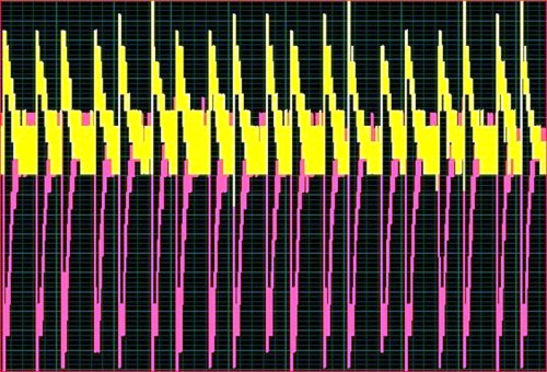
Image source: https://www.searchautoparts.com/motorage/electrical/locate-faults-can-network-these-tips-and-techniques?page=0,2
This waveform is reproduced from an actual waveform, and it shows the typical display when termination resistors are defective or missing from two-wire systems, or when there is a break in communication between two control modules.
In order to produce usable signals, all CAN bus systems typically use two 120 Ohm resistors between CAN-H and CAN-L lines. When these resistors are missing, or when broken wiring prevents effective communications over the system, the data bits that make up a message cannot be formed properly, and the signals that are created and transmitted reflect, or “bounce” off the ends of the CAN lines, which is what creates these characteristic waveforms.
One common mistake many technicians make is to disconnect control modules one by one in attempts to locate a defective control module. However, while this is often an effective way of identifying a defective control module, not bridging the CAN-H to CAN-H and CAN-L to CAN-L lines across the connector of a disconnected control module will not only produce the waveform above- it will also disable large sections of a CAN bus system, thereby making oscilloscope diagnostics of that system impossible.
Note therefore that since functioning termination resistors form the cornerstone of affective CAN bus system operation, these resistors must be checked as the first step in any diagnostic procedure that involves CAN bus system issues and oscilloscopes. Bear in mind though that while it is usually possible to test the termination resistors between pins 6 and 14 in the DLC, you need to be sure that the CAN bus gateway is not isolating the DLC from your test equipment. If it is, you might obtain a wildly inaccurate reading, or no reading at all, so be sure to consult a wiring diagram to be sure that you are testing the termination resistors through the actual CAN bus wiring- which is usually best done by back probing the connector of a suspect control module.
Despite their complexity, CAN bus systems are a fascinating aspect of modern automotive design, and it is our hope that this article has inspired you to learn more about how these systems work. In fact, as your knowledge of CAN bus systems improve, you will gain progressively clearer insights into how all the various control and management systems on modern vehicles interact, which will in turn, improve your ability to diagnose faults in individual systems and/or components.
