Although Mercedes-Benz has generally elevated forced induction systems on their engines to a high level of sophistication, some technical implementations of forced induction systems are less reliable than others, with the forced induction system on M274 engines being a prime example of an implementation that is not as robust and reliable as perhaps it might have been.
In this article then, which is the first instalment of a two-part article, we will discuss the various forced induction issues that are common on M274 Mercedes-Benz engines. Note though that while these engines were unusually prone to sudden and catastrophic piston failures more often than turbocharger failures, this article will focus only on forced induction system failures and malfunctions. Let us start with an-
NOTE #1: It might seem confusing to see the M274 engine mentioned alongside the M270 engine, but both the M274 and M270 engines are members of an extended family of engines that come in several variants and power levels. As a practical matter, though, apart from their displacement, the M274 and M270 variants are practically identical in all other respects, with the only meaningful difference between the two variants being that the M270 variant is fitted transversely in A-Class, B-Class, CLA-Class, GLA-Class, GLC-Class models to drive the front wheels.
By way of contrast, the M274 variant is fitted longitudinally in C-Class and E-Class models to drive the rear wheels through a conventional drive train consisting of a separate transmission and final drive.
NOTE #2: Repairs and servicing of the forced induction system on M274 and M270 engines should not be attempted without the benefit of OEM service information, which sometimes includes German words and terminology. One example is the German word “Abgasturbolader”, which is German for turbocharger. Moreover, in some sources, “Abgasturbolader”, is sometimes abbreviated to “ATL”, which is German shorthand for “Abgasturbolader”.
Although Mercedes-Benz replaced the M274 / M270 engines with the M260 / M264 series of engines in 2017, there are still great numbers of 1.6L and 2.0L M270/M274 engines (that were manufactured from 2012 to 2017) on the roads today. Below is a list of Mercedes-Benz models in which you could expect to find either a M270 or M274 engine-
- and, somewhat unexpectedly, in Infiniti QX30 / Q50 and Nissan Skyline Q60 / Q70 models as well.
In all applications, M274/M270 engines are fitted with IHI AL0071 and IHI AL0070 single-stage turbochargers for 1.6L and 2.0L engines respectively. In addition, in all cases, the turbochargers’ casings are integral parts of the exhaust manifold, meaning the manifold and turbocharger and exhaust manifold must be replaced as an assembly. Note that turbochargers’ waste gates are not available separately, which means that the turbocharger/manifold assembly must be replaced if the wastegate leaks or is damaged in some way.
In terms of operating principles, however, the forced induction systems on M274/M270 largely use the same components as those found on any other forced induction system, and the airflow pattern is also similar to that found on any other engine. However, the forced induction system on M274/M270 engines uses components that are generally not found on other vehicles. Consider the image below-
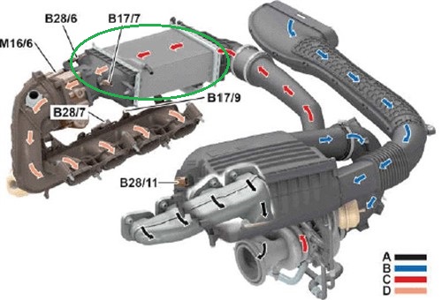
Image source; https://automotivetechinfo.com/wp-content/uploads/2024/01/charge-air-flow.jpg
This diagram shows the airflow pattern through the intake system on M274/M270 engines, with the blue and red arrows indicating the flow of cold and hot air, respectively. The part in the green oval is water-to-air the intercooler, but note that the intercoolers on some Mercedes-Benz vans are of the air-to-air type.
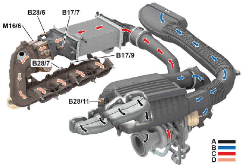
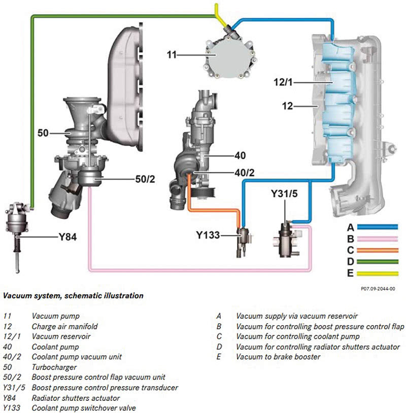
While the diagram above is largely self-explanatory, the diagram below shows some of the components that are not shown above-
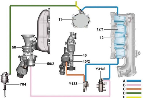
Image source; https://automotivetechinfo.com/wp-content/uploads/2024/01/boost-vacuum-circuit.jpg
The diagram shown above illustrates the vacuum control system in some detail, but let’s see what the different coloured lines and component labels mean. Consider the table below-
|
11 |
Vacuum pump |
Y84 |
Radiator shutter actuator |
|
12 |
Intake manifold |
Y133 |
Coolant pump switching valve |
|
12/1 |
Vacuum reservoir |
A |
Vacuum supply from vacuum reservoir |
|
40 |
Coolant pump |
B |
Vacuum supply for wastegate actuator |
|
40/2 |
Coolant pump vacuum unit |
C |
Vacuum for coolant pump control |
|
50 |
Turbocharger |
D |
Vacuum for radiator shutter control |
|
50/2 |
Waste gate actuator |
E |
Vacuum supply to brake booster |
|
Y31/5 |
Boost pressure transducer |
|
|
The diagram shown above also shows two components that are unique to Mercedes-Benz engines, these components being the-
Vacuum pump
Since the intake manifold vacuum is not constant, it is impossible to exercise fine control over the boost pressure control system. Thus, to overcome this problem, the forced induction systems on M274/M270 engines use dedicated engine-driven vacuum pumps that serve both the boost pressure control system and the brakes.
Vacuum reservoir
Again, since the manifold vacuum is not constant, it is very difficult to control the turbocharger's wastegate effectively under all possible engine operating conditions, especially during severe deceleration. Thus, to overcome this problem, Mercedes-Benz engineers added a dedicated vacuum reservoir that attaches to the intake manifold.
The practical advantage of always having a steady vacuum is that it enables the engine management system to exert not only precise control over the turbocharger's wastegate at all engine speeds but also that all control actions are always consistent and predictable because the engine management system does not depend on the manifold vacuum to control the boost pressure.
As a practical matter, the entire air intake system is optimised to ensure the lowest possible resistance to the air mass flowing through all parts of the system. In addition, the presence of a constant vacuum and the system’s ability to shed excess pressure at the turbocharger’s intake side reduces the chances that oscillating pressure waves could develop around the turbocharger’s impeller. In practice, oscillating pressure waves have a pronounced braking effect on the impellers’ rotational speed, which in turn, causes undesirable fluctuations in the boost pressure.
Having said the above, let us look at-
To improve both fault detection and the overall control of the intake system, the engine management system monitors the flow of air through the intake system, or as Mercedes-Benz puts it, the sequence of events that delivers pressurised air to the cylinders. As a result, many fault codes and drivability issues are linked to the monitoring of this sequence of events, as opposed to the random detection of faults and malfunctions that could occur anywhere in the forced induction system.
Thus, to make diagnosing faults and malfunction easier, the engine management monitors each of the three "areas of concern" separately, these areas of concern being boost pressure control, by-pass air, and intake air cooling. From a diagnostic perspective, it is critically important to understand the sequence of events that deliver pressurised air to the engine, because not all input data from one area of concern is shared with other areas of concern. Having said that, let us look at each area of concern separately, starting with-
Boost pressure control
Since the boost pressure control system is the most complicated area of concern, it requires and receives input data from the highest number of sensors and other monitoring devices. Briefly, these include the following-
By-pass air control
If the engine operates in a WOT (Wide-Open-Throttle) condition, maximum boost pressure is achieved at 0.7 to 1.5 bars, depending on the engine variant. At this boost pressure level, the compressor wheel spins at several hundred thousand RPM, so when the engine speed suddenly drops and the demand for pressurised air reduces suddenly, the compressor wheel’s inertia keeps it spinning at very high speeds until the reduction in drive pressure on the impeller reduces significantly.
As a result of the compressor wheel’s high rotational speed, it will continue to compress the air around it but since this air has nowhere to go, potentially destructive pressure waves begin to develop in the turbocharger's intake area. Therefore, to prevent damage to the turbocharger's compressor wheel and other components, the engine management system dumps excess pressure in the turbocharger's intake side through a bypass air valve that vents into the engine compartment.
Intake air cooling
Since the density of air is inversely proportional to its temperature, the forced induction systems on M274/M270 incorporate highly efficient water-to-air intercoolers that are tied into the low-temperature side of the engine cooling system. In a fully functional system, these intercoolers can consistently maintain downstream intake air temperatures at under 60 degrees C when the ambient temperature is around 20 degrees C, meaning that the engine’s overall performance is both optimized and predictable.
However, defects or malfunctions in this part of the system have a direct bearing on the temperature and by extension, the density of the intake air downstream of the intercooler, and so the engine management system monitors the temperature of the intake air downstream of the intercooler continuously via an electronic signal. When the amplitude of this signal changes by more than the maximum allowable level, the engine management system will either set appropriate fault codes and/or activate the low-temperature coolant circuit and the radiator cooling fans to assist with cooling down the intake air, which leaves us with-
In Part 2 of this article, we will discuss some common problems and issues that affect M274/M270 engines’ forced induction systems. We will also discuss some things to look out for when you are dealing with suspected faults on these forced induction systems, and provide some diagnostic tips and tricks that will help you resolve at least some forced induction issues on M274/M270 engines.
