In Part 1 of this two-part article, we discussed the general configuration of the forced induction systems on the Mercedes-Benz M274 and M270 family of engines. Now, in Part 2 of this article, we will discuss some common faults and malfunctions that affect the efficient operation of the forced induction systems on these engines, as well as provide some diagnostic tips and tricks that should help you diagnose and resolve the most common forced induction-related trouble codes on M274 and M270 engines. Let us start by listing-
The most common symptoms of forced induction system failures and malfunctions are largely similar across all applications but note that not all forced induction system-related malfunctions always produce fault codes. Nonetheless, some common symptoms include-
These kinds of complaints are usually, but not always, the result of one or more of the fault codes listed below-
P029900 – “The boost pressure of turbocharger 1 is too low”
This code usually indicates a mechanical failure of the turbocharger or one or more associated components.
P029909 – “The boost pressure of turbocharger 1 is too low”
This code indicates a failure of or malfunction in a component in the forced induction system that the engine management system cannot identify.
P029921 - “The boost pressure of turbocharger 1 is too low”
This code means that the amplitude of the signal generated by the boost pressure transducer is lower than the minimum allowable signal amplitude. Note that while this usually indicates an actual under-boost condition, this code could also indicate a defective or malfunctioning boost pressure transducer.
P023422 – “The boost pressure of turbocharger 1 is too high”
This code means that the amplitude of the signal generated by the boost pressure transducer is higher than the maximum allowable signal amplitude. Note that while this usually indicates an actual over-boost condition, this code could also indicate a defective or malfunctioning boost pressure transducer.
As a practical matter, the four trouble codes listed here cover a lot of ground in terms of their possible root causes and fixes, but before we get to specifics, note the following-
Although it is possible to diagnose the codes listed above (and others) without using Mercedes-Benz's Xentry diagnostic software, you will need a very high-end generic scan tool that a) can access all the control modules in the vehicle, and b) have bi-directional control functions. This is required because some components, such as the turbocharger's wastegate actuator can only be tested with a capable scan tool.
However, the advantage of using the Xentry diagnostic system is that the scan tool displays step-by-step diagnostic plans that almost resemble diagnostic flow charts, but in significantly more detail. If you do not have access to Xentry software, we strongly suggest that you obtain relevant Mercedes-Benz OEM service and repair information, including relevant wiring diagrams, pin-out charts, and the latest TSBs from the manufacturer to complement a generic scan tool’s abilities.
Having said the above, let us look at-
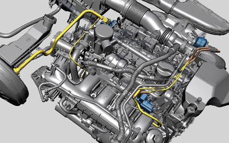
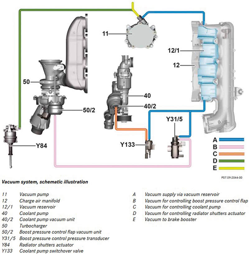
The network of vacuum lines that control the boost pressure is rather extensive, and it is often impossible to find or locate small vacuum leaks that can potentially affect the operation of the boost control system. Consider the diagram below-

Image source: https://automotivetechinfo.com/wp-content/uploads/2024/01/vacuum.jpg
The vacuum lines rendered in yellow (indicated by the red and green arrows) in this view may be the most accessible part of the vacuum system, but these lines are also the most likely to develop leaks because they are the most exposed to heat and vibration. Moreover, because they are routed so close to the engine, these lines are also susceptible to damage and perforation caused by chafing and rubbing against some engine components.
In older vehicles, these lines often develop hairline cracks and splits that are extremely difficult to locate without a heavy-duty smoke machine, or better still, a vacuum pump fitted with an accurate vacuum gauge, but checking and testing these vacuum lines to verify their integrity is always a useful starting point when diagnosing any forced induction system related codes on M274 and M270 engines.
Bear in mind that there are no known ways of repairing leaks in these lines that will last more than a few days or more commonly, only a few hours. The only reliable way of resolving leaks in these lines is to replace them with OEM or OEM-equivalent parts, along with all seals, grommets, and retaining clips, which brings us to-
In the previous article, we mentioned the fact that the forced induction system on M274 and M270 engines use two intake air pressure sensors- one immediately upstream of the throttle body, and another immediately downstream of the throttle body to produce more accurate readings of the air entering the engine.
So while the two pressure sensors will produce different readings when the engine is running, there is no air entering the engine when the engine does not run. Therefore, the two sensors should both register atmospheric pressure under KOEO (Key ON Engine Off) conditions and while it is rare to see two sensors registering exactly the same values, the difference between the two readings should not exceed about one per cent. If the two sensors generate readings that differ by more than about one per cent, one sensor (or sometimes both sensors) is/are defective.
However, be sure to obtain the current atmospheric pressure at your location from a reliable source such as your local weather station or airport before condemning one or both pressure sensors. Both sensors might be defective, albeit not always to the same degree, and so the engine management system will act on two erroneous readings, which will greatly affect the boost pressure.
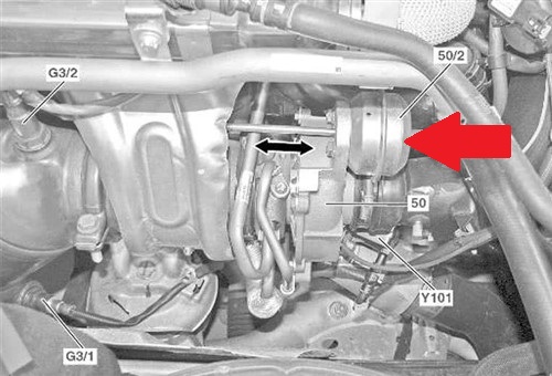
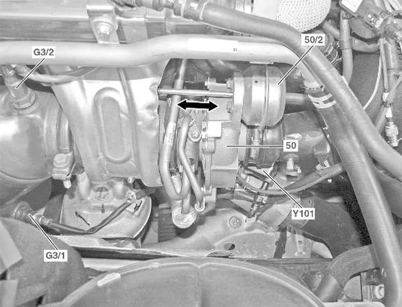
Image source: https://automotivetechinfo.com/wp-content/uploads/2024/01/mb-control-rod.jpg
This image shows the turbocharger waste gate’s vacuum actuator (indicated by the red arrow), which can fail to work as expected for several reasons. The two-headed black arrow indicates the control rod’s direction(s) of travel, which should always be equal in both directions.
However, the three most common reasons why the wastegate or its actuator might fail to work correctly are-
Note that, unlike other vehicles, on which it is often possible to move the control rod by hand to test its operation, this should never be done on any Mercedes-Benz engine because doing so could, and often does a) damage the vacuum actuator, and/or b) disturb/change the control rod’s adjustment setting.
The only way to test the operation of the actuator is to follow OEM service information to activate the vacuum system with a capable scan tool’s bi-directional function. Not following OEM-specified procedures during this test usually produces false, misleading, or inconclusive test results. For example, not using a calibrated vacuum gauge to check and verify that the boost pressure control transducer does pass vacuum while testing the wastegate actuator, may result in the wastegate actuator not working because the transducer is not allowing vacuum to pass through it.
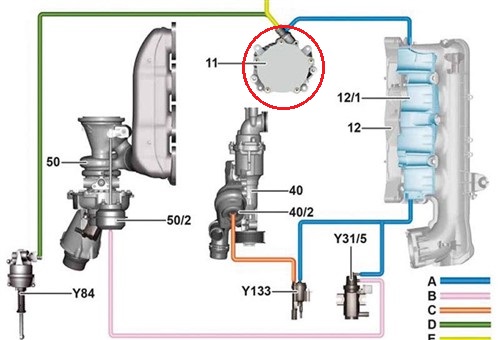
Image source; https://automotivetechinfo.com/wp-content/uploads/2024/01/boost-vacuum-circuit.jpg
This schematic shows the location of the engine-driven vacuum pump (circled in red) that supplies both the boost control and brake systems with a constant vacuum that is independent of the engine speed.
It should be noted that a reduced vacuum has a direct effect on both the brake and boost control systems, but what is more important to bear in mind is that vacuum pump failures resulting from oil contamination or mechanical failure are fairly common on M274 and M270 engines.
In practice, a new vacuum pump, or a vacuum pump that is in good mechanical condition will typically produce a vacuum of 28 inches of Mercury, which is equal to 950 mBar. However, it is rare to see a well-used vacuum pump producing a negative pressure of 950 mBar, but that is not necessarily an issue because Mercedes-Benz service information specifies a minimum allowable vacuum of 750 mBar.
So if the wastegate does not work as expected, be sure to take a reading of the vacuum the pump produces at the pump’s small outlet. If you find a vacuum of less than 750 mBar, remove the pump's cover to inspect it for evidence of engine oil contamination. Assessing mechanical damage is a little more difficult to do, but in all cases, the pump must be replaced if the vacuum it produces is less than the specified minimum.
On the other hand, if the pump produces an acceptable vacuum, inspect all the vacuum lines as well as all vacuum line junctions/joints for signs of damage and leaks that could affect the correct operation of the overall boost pressure control system.
As a prac5ical matter, the air by-pas valve is mounted on the intake side of the turbocharger and it acts like a mini dump valve to relieve excess pressure and violently oscillating pressure waves that develop around the compressor wheel and in air intake during deceleration.
This action reduces large fluctuations in the rotating assembly’s rotational speed during normal engine operation and as such, it reduces turbo lag significantly during large throttle inputs. However, the problem with the air by-pass valve is that it does not necessarily set fault codes when it fails or stops working as it should, which also does not necessarily produce noticeable drivability symptoms.
Moreover, the calibrations of air bypass valves are engine-specific, meaning that different engines within the M274/M270 family have air bypass valves that are calibrated differently. Therefore, be sure to consult OEM service information for details on how to test and assess the condition of the air by-pass valve in all cases where forced induction system-related fault codes are present on an affected vehicle. Failing to verify that the bypass valve works as expected can produce misleading, inconclusive, or downright wrong diagnoses for a variety of forced induction issues, which leaves us with this-
We hope that this article has given you some new insights into the forced induction systems of the M274/M270 family of Mercedes-Benz engines. Having said that, we must also stress the need for you to be sure of your diagnoses, because making a misdiagnosis, even inadvertently, could potentially have huge financial implications for you and your employer.
For example, some components, such as waste gates and wastegate actuators are not available separately. This means that replacing these components requires replacing the entire turbocharger/exhaust manifold assembly, which is a hugely expensive exercise. Not that any of us would make a misdiagnosis intentionally, but we are only human and we all make mistakes.
Therefore, to avoid making mistakes when diagnosing forced induction faults on M274 and M270 engines, we highly recommend that you a) obtain the relevant service information and b) study it carefully before you attempt a diagnosis. We say that not because the forced induction systems on Mercedes-Benz engines are inherently complicated but because making a mistake while diagnosing a Mercedes-Benz forced induction system could lead to very costly mistakes.
