The words “dwell” and “dwell angle” were in common use in the era of contact-breaker point ignition systems but they are by no means obsolete, and still have a valid and practical application in modern inductive ignition systems. This article will explain how the terms “dwell” and “dwell angle” apply to modern inductive ignition systems, but note that “dwell angle” has largely been replaced by the term “dwell time”, which as a practical matter, has the same meaning as the older term. Let us start with this question-
To understand the concept of dwell, it is necessary to understand how contact breaker points related to an ignition coil, and why a dwell angle was required.
In simple terms, a set of contact breaker points were acted upon by a lobed camshaft in the distributor, with the number of lobes on the shaft corresponding to the number of cylinders in the engine. In practice, the set of points were installed in such a manner that each cam acted on rubbing block, thereby opening the contact points by turns as the shaft rotated. If the points were installed properly, the contact points were in contact with each other when a cam was not in contact with the rubbing block.
When the contact points were closed, a low voltage current (typically battery voltage but sometimes less if a resistor was fitted to the system) passed through the points to the coil’s primary windings. When the points opened, the primary current was shut off, which was the triggering mechanism that created, or induced, the ignition current in the coil’s secondary windings when the magnetic field in the primary windings suddenly collapsed.
As a practical matter, the angle of rotation of the lobed distributor shaft between each successive opening of the points was known as the dwell angle, and was greatly influenced by how close to specifications the gap in the points were set, as well as by the degree of mechanical wear in the distributor, which brings us to-
Although modern inductive ignition systems contain no moving parts, there is still a need for sufficiently long dwell times to charge each coil in the system to the point where ignition of the air/fuel mixture becomes not only possible, but reliable as well.
However, the biggest challenges a modern inductive ignition has to overcome are the facts that-
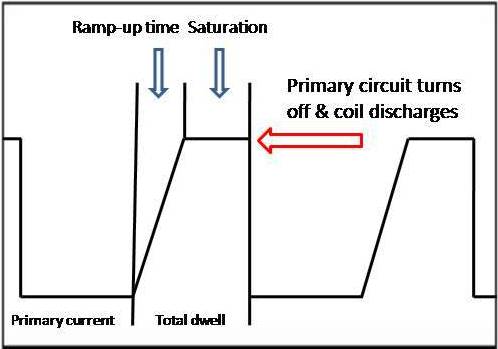
To address these issues, modern ignition systems are mapped, which is another way of saying that some of the components of an ignition event can be “adjusted”. Put in another way, this means that the ignition system can be electronically tweaked to deliver a spark of maximum strength and duration regardless of engine speed, which was not possible to do with contact breaker points, or even with some early versions of electronic ignition systems. Consider the diagram below-

This diagram is a simplified representation of a single ignition event, but note that the saturation point has been deliberately truncated for the sake of clarity; in an actual oscilloscope trace, this point would typically be the apex of an acute angle.
The purpose of the diagram is to illustrate the spark intensity vs. spark duration vs. coil charge, or dwell time problem. Consider this-
In a typical four-cycle petrol engine, the spark repetition rate can be calculated with this formula- t=120/ (N*RPM), where “t” is seconds, and “N” denotes the number of cylinders. Thus, for V8 engine running at 6000 RPM, we can calculate that 120 seconds divided by 48 000 (the number of cylinders multiplied by the RPM), yields a time of .0025, or 2.5 milliseconds between sparks.
Moreover, at 6000 RPM, the crankshaft rotates at a rate of 36 000 degrees per second (one rotation=360 degrees multiplied by the RPM, and dived by 60 to arrive at a rotation rate/second). Put in another way, the crankshaft rotates at a rate of 28 milliseconds per degree at 6 000 RPM, which we can calculate with this formula- 1/ (.006*RPM).
Given the above figures, it becomes abundantly clear that the time each coil has to reach its full charge is severely limited at high engine speeds, especially when one considers that at high engine speeds, the spark duration is typically about one tenth of a millisecond. Spark durations of longer than this is unlikely to deliver any useful energy, given that the optimum range for successful combustion is only a few degrees of crankshaft rotation. For instance, with spark durations of 0.8 milliseconds, the piston would be at about 30 to 50 degrees after top dead centre, which is way past the point where any useful energy can be extracted from the combustion event.
While the above might appear to be a digression from the main focus of this article, which is ignition coil dwell time, keeping these figures in mind will be helpful in understanding how modern ignition systems manage to provide each coil in the system with enough dwell time to accumulate enough energy to consistently deliver reliable ignition sparks. Here is how a modern ignition system does it-
In the context of modern inductive ignition systems, it is useful to consider dwell time as a progression of time, as opposed to a distance, or degrees of rotation of mechanical components as was the case with contact breaker point systems.
Nonetheless, the basic process of switching on a primary current to allow the primary coil windings to accumulate a charge, and then switching off the primary current to induce a magnetic field in the coils’ secondary windings to produce a spark is now accomplished by a complex switching of current between transistors and capacitors. Some details of this process are outlined below-
NOTE: The following explanations are of a generic nature and are intended for general informational purposes only. As such, this information should NOT be used in any diagnostic procedure without making proper reference to the relevant technical manual(s) that apply to the affected application.
In a typical mapped ignition system, the ECU has actual and effective control over the dwell time, and it performs this control in four primary semiconductor functions and several secondary monitoring functions. Let us look at the four main functions, starting with-
Pulse shaping
On most applications, an AC signal is fed into the triggering circuits by a pulse generator, but once the AC signal is recognized, it is converted into a square-wave digital signal. Note that the amplitude (height) of the square wave represents the current output from the pulse generator and remains constant since it is independent of the engine speed, while the pulse width of the square waveform represents the duration of the generator’s pulse output.
Dwell period control and voltage stabilisation
The dwell period is effectively managed by means of altering the time when the dwell period starts relative to the moment the coil discharges, in a process that is roughly analogous to changing the dwell angle on a contact points system by changing the point gap. While changing the start of the dwell time results in a reduced secondary discharge, this feature is required since it allows for faster, albeit limited dwell times to suit high engine speeds.
To prevent fluctuations in the power supply to the ignition module caused by changing charging outputs and the random use of electrical consumers, the primary voltage is stabilised by means of a dedicated voltage stabilising circuit in the ECU.
Primary voltage switching
Typically, the current entering the primary circuit is switched by a Darlington amplifier. In practice, this means that pulse signals leaving the dwell-time control stage are routed to a driver transistor that can be thought of as a current-control amplifier that switches the current from the ignition driver on and off at the proper times. As a practical matter, this function controls the heavy-duty power transistor at the output end of the Darlington amplifier’s output stage.
Pulse processing
From the time a signal is generated by the original pulse generator, to the time the spark actually jumps across the electrodes on a sparkplug, the electrical energy in the pulse undergoes several energy-state changes.
For instance, when the primary circuit is shut off, the charge in the secondary winding increases sharply until the actual spark is initiated. At this point, the energy that is required to sustain the spark decreases somewhat (since sustaining the spark requires less energy than it takes to sustain it) but this energy value is sustained until there is no longer sufficient energy in the coil to sustain the spark.
However, at the moment the spark is extinguished by the dissipation of the energy in the coil, the current in the secondary windings might rise slightly as the coil attempts to return to its high-energy state. Depending on the design of the ignition system as well as its overall condition, the remaining energy in the coil might oscillate a few times before the coil fully discharges. On an oscilloscope trace, this phenomenon can often be seen as a series of sharp peaks that drop off rapidly and progressively between the end of the sparking time and subsequent dwell period, which brings us to-
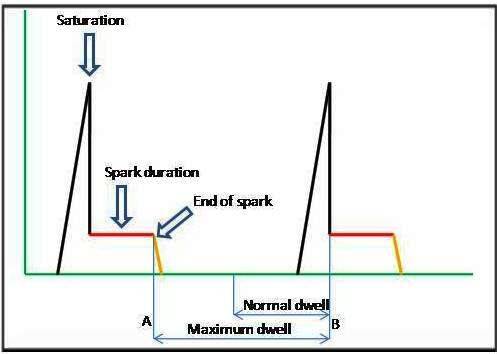
With contact breaker points, the ignition system was hampered by the fact that the dwell angle was constant over the engine’s entire operating range, since the distance between the cam lobes on the distributor shaft could not be changed to accommodate different engine speeds. While this problem was somewhat mitigated by using coils with low inductive properties, the problem remained that at high engine speeds, even a low induction coil could not always be charged up sufficiently to deliver high-energy sparks consistently. Consider the diagram below-

This diagram is a simplified representation of the dwell time between two successive ignition events. The green vertical line represents the secondary voltage in kV, while the horizontal green line represents the elapsed time between ignition events, which is measured in milliseconds.
In this diagram, the upper thin blue arrow represents the dwell time at low engine speeds, and while its short duration relative to the maximum dwell time might appear to be counterintuitive, this is possible because the time periods between ignition events are longer as a result of the low engine speed.
However, as engine speed rises, the time periods between ignition events become shorter, which has a corollary reduced dwell times, which in turn, reduces the secondary voltage and therefore, the strength and duration of the ignition spark. To prevent this, the ECU moves the starting point of the dwell time progressively along the arrow A-B, up to point “A”, which represents the maximum dwell time for any particular ignition system.
Increasing the dwell time beyond point “A” serves no practical purpose, and is in fact detrimental to ignition because the duration of the spark is reduced. However, it should be noted that the adjustment increments of the dwell time toward point “A” is greatest between idling and about 4 000 RPM, since this provides the highest secondary voltages for the purposes of emission control during combustion at low engine speeds. Above about 4 000 RPM, adjustments of the dwell time becomes progressively smaller to provide a near-constant secondary voltage up to the spark limit of the system, which is about 15 000 sparks per minute on most OEM ignition systems.
While all of the above is admittedly an oversimplification of a complex process, it should nevertheless serve to illustrate that dwell time not only plays a critical role in efficient engine operation but that dwell times can also be used as a valuable diagnostic tool, even in the absence of relevant technical information and/or reference data such as waveforms.
If an engine is in excellent mechanical condition and the ignition system is fully functional, the oscilloscope traces for each ignition coil will be practically identical. Therefore, any observed differences in secondary voltages, spark durations, and dwell times between two or more traces can serve as quick and reliable indicators of bad coils, worn/unsuitable/incorrect spark plugs, defects in ignition drivers and/or igniters, and even poor combustion as the result of compression losses or other issues.