When we stop to think about how modern, OBD II-compliant vehicles are programmed it turns out that several incongruities jump out at us. For instance, of the more than 100 million lines of computer code that make a modern vehicle work, less than one per cent of the total amount of coding is dedicated to fuel control, which is strange, given that fuel injection was invented precisely to improve fuel control on modern engines.
In all fairness, fuel injection does have major advantages over carburettors, but the fact is that the monitoring, management, and ultimate control of fuel delivery systems on modern vehicles are still rather ineffective. As a result, even the most advanced internal combustion engines still require enormously expensive and complicated exhaust after-treatment systems to remove excessively high hydrocarbon loads from exhaust streams that could have been much cleaner, to begin with. Thus, in this article, we will take a closer look at why fuel injection systems are not as efficient as they perhaps might have been. Let us start by stating-
The oldest among us will remember one particular condition that affected almost all early iterations of fuel injection systems. While all vehicles were affected by this issue, GM products, in particular, were perhaps the worst affected with a rough idle condition when the engine was in closed-loop operation. Consider the diagram below-
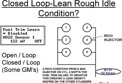
This diagram shows a simplified schematic representation of the fuel management system of a circa 1989 GM V6 engine. The actual engine that this diagram pertains to is not important here, since all GM engines, and in fact, all engines made by all manufacturers from this era followed the same general pattern. So what does this diagram show?
In simple terms, it shows the severe lack of resolution* in the systems’ control mechanisms(s), which was arguably the single biggest drawback of the fuel injection systems from this era.
* This remains an issue even in modern fuel injection systems.
Let us look at this diagram in some detail. As shown here, the injector on cylinder number four has some sort of problem that causes a rich condition. The single narrow-band (upstream) oxygen sensor detects the rich condition, and as result, the ECU removes fuel from the air\fuel mixture, thus causing lean conditions on the five good cylinders. This, in turn, causes a rough, "choppy" idle quality, which disappears when the engine speed increases to above idling speeds.
It should be borne in mind that when this issue first presented itself in our bays, those of us who had cut our proverbial teeth on carburettors, copper plug leads, and distributors that worked with points and condensers were in the middle of a steep learning curve. Therefore, few of us had any idea that the ECUs of the time had no way of identifying which injector was defective, so they compensated for the rich mixture by leaning out the fuel mixture for all the cylinders.
The opposite also happened. For example, in cases where a single injector had become restricted, the single narrow band oxygen sensor detected the lean condition, which resulted in the ECU enriching the air/fuel mixture for all the cylinders, which causes both a rough, “choppy” idle quality, and extremely poor fuel economy.
This writer can recount many tales of bitter battles fought with a) engines that idled badly, and b), with customers that often refused to pay up for a set of injectors just because we "thought" that one or more injectors might be defective in some way.
Of course, the real problems were that we did not yet fully understand how fuel injection systems worked, and how they were controlled. For example, few of us understood at the time that the narrow band oxygen sensor in use then could not detect air/fuel mixtures that were richer or leaner than about 20 per cent of stoichiometric, which largely explained why we saw so few injector-related codes. We did see plenty of misfire codes thirty years ago, but it took us a while to figure out that most of these codes were related to injector issues, as opposed to ignition or mechanical problems.
Before we move on to the next development in fuel injection systems, it is perhaps worth noting that during the time that both cylinder banks on V-type engines shared a single upstream oxygen sensor, we could not use fuel trim values as definitive diagnostic aids. This was because when an ECU adapted injector pulse widths for all the injectors to compensate for mixture errors the adaptations affected both banks equally, which all but wiped out any potential diagnostic value fuel trim figures might have had, which brings us to-
The next major development in fuel injection came in the early to mid-1990s with the large-scale adoption of sequential fuel injection systems. Unlike previous systems that fired half of the injectors on one engine revolution, and the other half on the following engine revolution, sequential systems injected fuel only when the intake valve on a cylinder was open; hence, the term “sequential” because each injector was activated sequentially, according to the engine’s firing order.
As a practical matter, this type of injection strategy only became possible because of (then) recent improvements in computing speeds and sensor responsiveness. In fact, by the mid-1990s, computing power had reached a level where some manufacturers began experimenting with multiple injection events per cylinder at engine idling speeds.
On a practical level, though, the greatest advantage of sequential systems was that they greatly improved fuel economy and engine performance while reducing exhaust emissions, at the same time. However, for all their technical sophistication, sequential fuel injection systems still could not identify and/or isolate defective fuel injectors that cause abnormal combustion in one or more cylinders.
Nonetheless, one particular refinement that sequential systems did have over older systems was that instead of a single upstream oxygen sensor that interpreted the air/fuel mixture for the entire engine regardless of the number of cylinders present, modern sequential systems now employed an upstream oxygen sensor for each bank of cylinders. While this added some resolution to the faultfinding capabilities of the fuel delivery system, four-cylinder engines still used only a single oxygen sensor.
This era also saw the introduction of wide-band, heated oxygen and air/fuel ratio sensors that could detect air/fuel mixtures as lean as 18:1, and mixtures as rich as 1:1- not that any engine could run on a mixture as rich as 1:1, but still. From a diagnostic perspective, however, the use of two upstream oxygen sensors now made it possible to draw somewhat definitive diagnostic conclusions from differences in fuel trim values between two banks of cylinders on V-type engines, although diagnosing fuel trim issues on four-cylinder engines were still somewhat of a guessing game, which brings us to-
From the literature dating back to the mid-1990s, it was clear that the single most important criterion that determined how effectively (or otherwise) the fuel injectors operated was fuel pressure. From a design perspective, this was a reasonable point of departure because a) fuel is largely incompressible, and b), the injection of a measured amount of fuel into the intake manifold* through a fixed orifice should produce a predictable drop in pressure in the fuel rail(s).
* Note that this assumes that the ECU takes proper account of all variable and environmental factors like (among others) the ambient air temperature, current atmospheric pressure, engine coolant temperature, and throttle position.
Thus, in theory, the operation of sequential fuel injection systems, and by extension, the proper fuelling of an engine was premised on the idea that if the fuel rail(s) could be fed with a continuous supply of fuel at desired pressure, each injection event should reduce the overall pressure in the fuel rail(s) by a predictable and measurable amount. As it turned out, however, the theory was often wildly different from the desired practice. Here is why-
During the mid to late 1990s, and even into the early 2000s, most fuel injection systems used fixed-speed pumps that delivered fuel at a constant rate and pressure. This ensured that the fuel injectors were always supplied with fuel at a higher pressure than they needed to work reliably, and all excess pressure was vented back to the fuel tank via a simple spring-loaded pressure regulator.
Thus, to maintain the desired pressure in the fuel rail, several things had to happen. These were that-
While sequential systems worked well enough their only advantage over previous designs in terms of diagnostics was that by using two upstream oxygen sensors on V-type engines it became possible to compare fuel trim values from each bank. However, if an injector failed and caused a rich condition on say, bank 1, the ECU would lean out the mixture on the good cylinders on that bank. Similarly, if a lean condition arose in one cylinder on bank 1, the ECU would enrich the mixture on the good cylinders on bank 1.
This sometimes created grossly misleading fuel trim values because enriching or leaning out good cylinders created an overall fuelling imbalance across all the cylinders. For instance, fuel trim values for bank 1 could be say, -25 per cent, while the fuel trim values for bank 2 could be normal. On the other hand, fuel trim values for bank 1 could be +25 per cent, while the values for bank 2 could be normal.
Adding or subtracting this much fuel from the mixture on one bank, but not doing the same on the other bank could result in all manner of drivability issues such as poor fuel economy, rough or erratic idling, poor acceleration, misfiring, frequent engine stalls at low engine speeds, and other issues like recurrent catalytic converter failures. So, how did we diagnose these issues?
It was not always easy, but in the case of lean conditions, a good starting point was always to verify that there were no air leaks present on the affected bank of cylinders. If a rich condition was present, a good starting point was to verify the actual fuel pressure with a scan tool. In all cases, this was followed by checking misfire counters on all cylinders, which was in its turn, followed by a compression test to verify that cylinder compression was within specifications on all cylinders if there were no ignition codes present.
If all spark plugs were normal and moving ignition coils around did not cause the misfire (if present) to move to another cylinder, we performed a fuel pressure drop test under KOEO (Key On Engine Off) conditions. This test involved activating the fuel pump to run continuously, and then activating each injector via the scan tool while monitoring the fuel pressure with a dedicated fuel pressure gauge tied into the fuel system. The theory was that since fuel is incompressible, activating an injector would produce a measurable drop in the fuel pressure, but this test produced inconclusive results more often than not.
One other and somewhat similar test involved replacing the pressure gauge with a transducer and then monitoring the fuel system pressure with an oscilloscope. In this test, the theory was that as each injector was pulsed while the engine ran, each injection event would produce a dip in the pressure waveform, but the problem with this test was that it was sometimes very difficult to tie a transducer into the fuel system on some makes and models. Moreover, even if one succeeded in placing a transducer so that no fuel leaked, the pulsing injectors created oscillating pressure waves in the fuel system that almost always masked, and sometimes, obliterated any useful diagnostic data in the waveform.
So while the above tests usually did not work to identify injectors that caused lean conditions, we did have a way to identify injectors that caused rich conditions. This test involved monitoring the oxygen sensor on the affected bank of cylinders with the engine running; if we deactivated an injector with a scan tool, the oxygen sensor would register a momentary, but a major shift towards lean if the injector were good. If the injector were defective or leaking, deactivating it would not produce the lean shift, but replacing a single injector on high-mileage engines was generally not a good idea because this sometimes caused borderline defective injectors to start leaking.
Thus, absent all other possible causes of wildly uneven fuel trim values between banks of cylinders, we still ended up replacing fuel injectors as a remedy. Of course, engine designers could have removed almost all of the guesswork from diagnosing this type of issue simply by giving each cylinder its own oxygen sensor but instead, and starting in 2011, some manufacturers introduced a new fuelling strategy known as Individual Cylinder Fuel Control, which became legally mandated in the US domestic market in 2014. Let us look at-
The biggest problem with ICFC is not so much with what it is, but rather with what it is not. From the name of the system, one could reasonably presume that this iteration of fuel injection technology can monitor, control, and adjust the air/fuel ratio of each individual cylinder independently of all or any other cylinder(s) in the engine. Sadly, ICFC systems cannot do that but if they could, they could have made spark-ignition engines at least 20 per cent more efficient, reduced exhaust emissions by about 40 per cent, and increased fuel economy by almost 50 per cent. So, what is the problem?
The problem is simply this; previous iterations of fuel injection and diagnostic technologies did not take account of things like-
- and many other factors that produce unequal combustion between the cylinders on any given engine.
We stated elsewhere that like other fuel injection systems, ICFC systems can neither identify fuelling imbalances on individual cylinders nor compensate for them in individual cylinders. However, the upside is that ICFC systems do not only identify fuelling imbalances caused by issues that other systems take no account of, but they also identify smaller imbalances than other systems can. Here is the short version of how ICFC fuel injection systems work-
It is important to understand that ICFC systems do not use additional parts and/or components. These systems use only the parts and components that occur in "normal" sequential fuel injection systems, but there is one major difference in how wide-band oxygen sensors are used. In “normal” systems, the wide-band oxygen sensor only monitors the composition of the exhaust stream, with its changing output current being the trigger that initiates adaptations to the injector’s pulse widths.
In ICFC systems, however, the wide-band oxygen sensor also measures the frequency (typically, between 2 and 5 Hertz), or density/strength of the exhaust pulses, this value being a good indicator of the quality of the combustion process in each cylinder. Here is the short version of how this control aspect works-
In practice, ICFC systems also track the movement of the pistons, just like normal sequential systems do, but in the case of ICFC systems, the ECU is programmed to detect exhaust pulses in the exhaust system via the upstream oxygen sensor. A discussion on the complexities and evolution of the mathematical algorithms that underpin this ability fall outside the scope of this article, but essentially, the ECU creates virtual pressure sensors (via its programming) for each cylinder and uses these virtual pressure sensors to track the exhaust top dead centre of each piston.
On an oscilloscope, each exhaust pulse is rendered as a square waveform, but unlike the square waveforms of say, wheel speed sensors, both the amplitude and frequency of the exhaust pulse waveforms change as the engine speed changes. So, under steady engine speed conditions, and assuming that all combustion pressure values are near-identical, the oscilloscope will record a series of square waveforms that are equal in amplitude, which would indicate that no fuelling imbalances exist between cylinders.
Nonetheless, to account for variables, the ECU does not record each variation in the exhaust pulses during an engine cycle. Instead, the ECU compares the average frequency and amplitude of the exhaust pulses with the average recorded over the previous ten drive cycles, which data is (in most cases) accessible in Mode 6 on most scan tools. It is, however, important to understand that ICFC systems neither replace nor augment existing misfire detection systems.
Conventional misfire detection systems typically record variations in the crankshaft’s speed that exceed about 2 per cent of the crankshaft’s average speed over a single engine cycle, while ICFC systems can detect cylinder power imbalances (via exhaust pulses) that produce crankshaft speed variations that are as small as 0.1 per cent of the crankshaft's average speed over an engine cycle. Thus, to differentiate between causes that produce actual misfires, and causes that produce small differences in combustion pressure between cylinders, ECUs will set codes like P219A (and/or a few closely related codes) that indicate either fuelling imbalances or cylinder power contribution imbalances.
So, you may ask what the purpose of ICFC systems is if they cannot compensate for fuelling issues on individual cylinders. Well, the single biggest advantage of ICFC systems involves the fact that they can detect and report issues that affect exhaust emissions negatively much sooner than conventional injection systems can- even if the term Individual Cylinder Fuel Control is a bit of a misnomer.
Thus, issues that would have gone undetected previously will illuminate CHECK ENGINE lights much sooner, which in theory, at least, should motivate drivers to have the cause of the warning light investigated sooner, which leaves us with this-
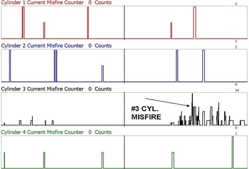
Image source: https://www.autoserviceprofessional.com/ext/resources/2022/04/01/Cylinder-Fuel-Control-Strategy14-web.jpg
This image shows historical misfire data on a GDI 4-cylinder GM engine equipped with ICFC. In this example, cylinder number 3 has accumulated many cylinder power/fueling imbalances as the result of excessive carbon build-up on the intake valve on cylinder number three. Note that while the problem in this example is older than the ten immediately previous drive cycles, the ECU had only stored data for the past ten drive cycles.
Sadly, though, the solution to historical power or fuelling imbalances is not always as easy as cleaning the carbon off intake valves, but on the upside, Mode 6 data will almost always provide evidence of a problem in cases where there are no discernible drivability issues present, or where drivability issues/complaints are difficult to replicate. Of course, finding and fixing the root causes of codes like P219A if the intake valves are clean remain challenging, but once you understand the limitations of fuel injection systems, it often becomes easier to fix fuelling issues if you concentrate on what fuel injection systems cannot do, as opposed to what we think or assume they should be able to do.