We all have certain core skills that make us better at some things than others, but in this writer’s experience all, or most mechanics and technicians also have one other thing in common, and that is being called upon to do something that falls outside of their comfort zones. Therefore, this writer’s brake system specialist was somewhat less than pleased when in the absence of the workshop’s diagnostician, he was called upon to diagnose and repair a severe a parasitic current draw issue on a conventional 2017 Honda Civic that we had not seen in the workshop before. In this article, we will explain how, when all else failed he eventually did it with an oscilloscope, which is not something that is typically used to find parasitic current draws. Let us start with stating-
The first thing this customer told us when he presented his immaculate vehicle was that it had been involved in an accident about a year before, and although the front end was severely damaged, he'd had no issues of any kind since the vehicle was repaired by a local body repairer. He also stated that the battery drain issue started about three weeks prior and that now, the battery drained from fully charged to a point where it would not crank the engine in less than six hours.
The customer also said that he was a “bit of a DIY mechanic” and produced some printouts from his laptop-based code reader that did not show any stored trouble codes except for some that related to low system voltages. His code reader did not find any codes relating to the charging system as a whole in general, or any charging system component in particular, apart from the battery’s low state of charge. Of course, the absence of charging system and/or communication codes did not necessarily mean that such codes were not present; it only meant that his generic code reader might not have been able to access the serial communication systems to extract them.
The customer accepted this in good grace, but could not wait for us to run a comprehensive diagnostic scan with our Honda-specific tools, so we offered to drop him off at his office, and to let him know what we found- when we found it. We were in the middle of a particularly busy time just then, and the brake system specialist was busier than most. Nonetheless, he parked the vehicle in his generously sized bay and prepared his plan of attack. This is how it went-
Since the brake specialist was outside of his comfort zone, he started his attack by running a full diagnostic scan in an attempt to reduce the problem to its simplest form. This approach has served him well when chasing down faults in brake systems, so it seemed like a good place to start. However, the only thing he learned was that apart from the battery’s state of health that was at 82%, there were no other historic, pending, or active codes present.
Next, he connected our diagnostic battery charger to the vehicle, which only told him that the battery was in excellent condition, and checking the battery replacement history showed that a battery reset procedure had been performed successfully when the current battery was installed two weeks before. The charging system also performed well and within acceptable parameters, which meant that resolving this problem was not going to be easy.
Not wanting to let a good challenge go to waste, the brake specialist then switched off the ignition, removed the key, and then removed the negative battery cable to connect a non-powered test light between the terminal and the battery post. The test light glowed brightly, so there was indeed a problem present. Reconnecting the battery cable and attaching an amp clamp showed a current draw of just more than 200 milliamps, which was surprising, but not as surprising as the fact that the current draw showed a rhythmic or cyclical increase to 515 milliamps. Thinking that his amp clamp might be defective, the brake specialist repeated the measurement with a high-end digital multimeter, which confirmed the cyclical current variation, at which point we notified the customer that he would not be getting his vehicle back that day.
Thinking at first that an issue in the security system and its blinking red warning light might be causing the rhythmic current variation, the brake specialist compared the time-lapse between current draw peaks with the blinking light. This turned up nothing since the time lapse between the current peaks was about twice as long as the time lapse between flashes of the security light, and all dome and courtesy lights were off, so clearly, it was time to-
On the face of it, there is no earthly reason why a parasitic current draw would be cyclical unless of course, the draw is taking place in a controlled circuit of some kind. However, when a vehicle is switched off not many controlled circuits are active, apart from the security system and some other systems like the navigation, telephony, and perhaps some infotainment systems. Moreover, these kinds of circuits/systems typically do not draw currents as high as 500 milliamps when they are in standby mode, so something else must be going on.
By this time, the brake specialist was asking for assistance and/or advice from colleagues, so it was suggested to him that in some cases, some control modules could exhibit this kind of rhythmic current draws when they are a), not grounded properly, or b), not being supplied with sufficient voltage and/or current.
Therefore, the best thing to do would be to connect a clean power supply to the battery, and then to check if the problem persists, which it did. However, since these kinds of issues typically set communication codes, both ground and power feed issues were ruled out as a cause because no communication codes were present.
One other suggestion involved using a contact-less current probe to narrow down the search area, but since this required removal of much of the dashboard to access most wiring, the brake specialist chose instead to attempt to identify the implicated circuit by performing voltage drop tests across all the fuses. The thinking behind this plan of attack was that if a particular fuse showed the rhythmic current variation, pulling that fuse should identify the problem circuit. This plan worked, but it turned out that the implicated fuse was Maxi fuse that protected multiple circuits, none of which was labelled in the fuse box.
While pulling the Maxi fuse interrupted the current draw, interrupting the current draw did not cause any electrical consumer not to work when everything that could be turned on, was turned on. This implied that at least some parts all of the circuits that were protected by the Maxi fuse must be energised when the vehicle was switched off, but while this made perfect sense, identifying the actual problem circuit was not going to be easy.
An internet search for this particular problem on late model Honda Civics turned up nothing of any diagnostic value, but by this time it was late afternoon, and the light in the workshop had dimmed noticeably, which turned out to be fortunate. Why was this fortunate, you might ask? Well, it was fortunate because while the brake specialist was sitting behind the steering wheel pondering the problem, the corner of the workshop where the Honda was parked grew progressively darker, which revealed the source of the problem- a faint, but unmistakable brightening of the driver information centre in a rhythmic pattern that matched the cadence of the current draw. No particular warning lights lit up- it was more like the area behind the main instruments lit up somewhat in a definite pattern, and the light then diffused through the entire instrument cluster.
This writer had never seen anything like this, and neither had anyone else in the workshop, but everyone agreed that resolving this problem would require both OEM service information and a large- scale wiring diagram, neither of which were available ten minutes before closing time. It is perhaps worth noting at this point that the brake system specialist was a specialist for a reason; he was known to be resourceful, and his ability to think critically under pressure was almost legendary- at least in his workshop, so he proposed-
The idea behind the plan was to a) obtain a visual representation of the current draw by obtaining a waveform of the current, and b), to see if the waveform was of any diagnostic value. Hooking up his scope to the battery negative cable only took a minute, and this is what we saw-
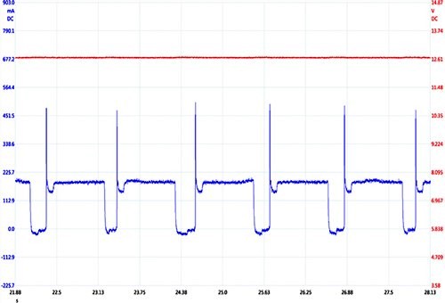
Image source: https://www.searchautoparts.com/sites/www.searchautoparts.com/files/images/ma0919-mag2%20copy.png
You will likely agree that this waveform is strongly reminiscent of an injector duty cycle, but since the engine was not running, the waveform could not be caused by an injector duty cycle. Nonetheless, now that we could see the "shape” of the current flow, we took a screenshot of it and uploaded it to this website via our current account, also asking if any members have seen this particular waveform before. We then made sure our diagnostic battery charger was properly connected to the Honda's battery, shut up shop, and went home.
Early the next morning we found a response to our query from a technician in the UK. This response included an example of a waveform just like ours, and while the amplitude of the current draw was not as high as ours was, it had precisely the same frequency and overall “shape”. Moreover, the responder also mentioned that before doing anything else, we should attempt a reset procedure of the infotainment system since this had on occasion cured the problem for him on other Honda models. Finally, the responder also mentioned that this reset procedure should only be attempted if we had access to original OEM service information because getting the steps wrong could damage some control modules.
Long story short, we purchased a short-term subscription to an online resource that provides OEM TSB’s and service information and attempted the reset procedure, which failed to complete. This was not all bad since it seemed to confirm that there was something wrong with the infotainment system but since it did not seem to have a dedicated fuse, we were obliged to isolate the system from the vehicles’ wiring.
Using our recently purchased wiring diagram and connector pin-out charts, we managed to isolate most of the infotainment system, and the current draw went away. To make sure we were not dealing with a fluke, we reconnected everything we had disconnected, and the current draw returned, but the brake specialist noticed signs of corrosion and rust under the dashboard while he was reconnecting systems.
It seemed that we had found the proverbial smoking gun, so we contacted the Honda’s owner to find out if the vehicle had ever leaked, or if the windscreen had been replaced during the collision repairs a year before. It turned out that the windscreen was severely damaged in the crash, but since he’d had some insurance issues at the time, the damaged vehicle was exposed to the elements (which included some heavy rain) for a few weeks before it was removed to the body shop, which information provided-
So there we had it; water had leaked into the vehicle through the damaged windscreen, and some of that water leaked into some parts of the infotainment system where it formed rust and/or corrosion. The strange thing was that the rust, which we found in the radio when we removed it to verify water damage, took so many months to start affecting some circuits, but stranger still, the radio and the entire infotainment system worked perfectly, despite causing a severe parasitic current draw.
We were never able to explain the cyclical nature of the current draw but to make sure that we were dealing with a corrosion issue, and not something else like an intermittent failure of an electronic component, we reconnected the infotainment system a second time and the current draw returned. Given the eye-watering cost of a new infotainment system, the customer accepted that the only reliable remedy was the replacement of the infotainment system with remarkable stoicism, and supplied us with a used system a few days later.
Installation of the replacement system was not exactly trouble-free, but we did manage to make it work after a full day's work and to verify that everything was as it should be and that we did not screw up anything else, we scoped the vehicle a second time to verify the repair. This is what we saw-
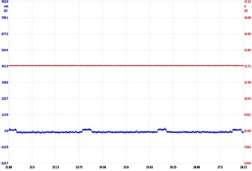
Image source: https://www.searchautoparts.com/sites/www.searchautoparts.com/files/images/ma0919-mag2%20copy.png
This time, there was no trace of the current draw, and the little bumps shown here are minute draws caused by the blinking security warning light. We had found and fixed the problem, albeit with some guidance from a technician on the other side of the world. However, had it not been for the brake specialist that came up with the genius idea to scope the current draw, we would likely not have found the problem. This would have been because a) we did not understand what we were looking at, and b) we did not know which questions to ask because we did not understand the nature of the problem, which, at the time, left us with this-
This particular current draw taught, or reminded us that no matter how well we know our jobs there will always be situations or problems that challenge our collective knowledge and experience in the worst possible way. We also learned that while conventional test methods usually work to find parasitic current draws, these methods are sometimes not enough and that an unconventional test method may sometimes produce usable diagnostic information quicker than established methods can.
So when next you are faced with an exceedingly difficult or perplexing current draw issue, why don't you scope the current flow to visualise the "shape" of the problem? You have nothing to lose and everything to gain; this method worked for us, and it will work for you, too.
