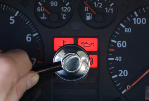

If you are new to the car repair industry, you have no doubt wondered why the electrical systems of modern cars have to be as complex as they are. The answer is simple, really; the complexity of modern automotive electrical systems is the direct result of modern cars having to satisfy increasingly stringent emissions regulations.
However, modern emissions regulations also dictate that to be fully OBD II compliant, all vehicles must have the ability to monitor and control all aspects of emission control in manageable chunks via dedicated readiness monitors, which when viewed objectively, removes much of the complexity of modern emission control systems. This article will explore readiness monitors in terms of what they are, what their purpose is, as well as describe some monitors that apply only to compression ignition applications, starting with this question-
Put simply, readiness monitors represent a set of self-diagnostic tests that all OBD II compliant vehicles must be able to run and complete successfully to ensure that that vehicle is able to comply with current emissions regulations. In jurisdictions where compulsory periodic emissions testing are a legal requirement, the object is not to test the vehicle’s actual emission levels; the object is to verify that the vehicle’s ECU is able to execute all required monitors successfully.
Nonetheless, regardless of whether or not compulsory emissions testing is required, the failure of one or more readiness monitors to run/and or complete (provided all enabling conditions have been met) is indicative of failures/defects/malfunctions in parts/components/control circuits that effect emission levels directly. Moreover, failures/defects/malfunctions that prevent monitors to run have the potential to cause secondary damage: an extreme example would be if the catalytic converter overheated and caused the vehicle to catch fire because a fault that prevented the catalytic converter monitor from running was left unresolved, which brings us to this question-
Most modern vehicles have between eight and fifteen monitors, with some that apply only to compression ignition engines. In addition, some monitors run continuously while the engine is in operation, while others only run at certain times, and only when their enabling conditions have been met. In some cases, a particular monitor’s enabling conditions can include the requirement that one or more other monitors must have run and completed successfully, that the fuel tank must contain a specified amount of fuel, or that the engine coolant temperature must be above a minimum threshold for a specified time.
However, all applications have one particular monitor in common, which is the-
This monitor is executed by the ECU whenever the engine is running, and its function is to check for faults/defects/malfunctions in any component(s) and/or control circuits that provide either input or output data to the ECU that has the potential to affect emissions levels. Note though that this monitor only tests components and/or circuits that are not monitored by a dedicated readiness monitor.
As a practical matter, and at a minimum, the comprehensive component monitor checks circuits for both continuity and the range of signal voltages, and where possible, also for output signal rationality/functionality. For instance, some analogue signals, such as those from the throttle position and engine coolant temperature circuits are tested for short or open circuits, as well as for signal values that may be out of range. An example of this would be an engine coolant temperature value of say, 600 degrees Celsius, which is clearly out of the accepted range. Similarly, digital signals such as the crankshaft position are checked for rationality; this would involve comparing the input signal to the actual engine speed as determined by other sensors and/or systems.
Some outputs are also checked for open or short circuits via dedicated feedback circuits, such as those found on some ignition coil drivers. Additionally, the actual operation of some components, such as an idle air control valve is tested by monitoring the actual idling speed, and comparing that value with the desired or target idling speed. Note though that while the comprehensive component monitor tests many components and systems on a continuous basis, some tests can only be performed under appropriate conditions, such as the operation of the torque converter lock-up clutch and/or shift solenoids that can only be tested during an actual gearshift.
While the comprehensive component monitor runs continually when the engine is running, it must not be confused with any of two other monitors that also run continuously while the engine is running. Below are some details of the-
The following two monitors have the task of monitoring systems that are crucial to efficient engine operation, and as such, the faults they detect should not be ignored or left unresolved for any length of time. Below are some details of these monitors-
Fuel system monitor
The primary function of this monitor is to evaluate the actual air/fuel mixture being combusted in terms of how closely it matches the ideal 14.7:1 air/fuel ratio. When the oxygen sensors enter closed loop operation, this monitor keeps track of how well the ECU is able to make adjustments to fuel trims during normal driving conditions. Corrections to fuel trims are based on look-up tables stored in the ECU, and provided that no DTC’s are stored, and the EVAP system is not purging fuel vapours into the engine, the fuel system monitor will run continuously while the engine is running.
It should be noted however that the fuel system monitor’s function is not to make adjustments to fuel trims; its function is purely to monitor the efficiency of the UCE in terms of making fuel trim adjustments by altering the injectors’ pulse widths. For instance, if the fuel system monitor detects that the ECU needs to make adjustments to the fuel trims to achieve a 14.7:1 air/fuel ratio that will exceed a maximum or a minimum allowable value it will set a pending code. If the excessively rich or lean condition occurs again during the subsequent three warm-up cycles, an active DTC will be stored and a warning light will be illuminated.
Misfire detection monitor
Since some types of misfires have the potential to increase emissions to beyond acceptable limits, the misfire detection monitor runs continuously while the engine is running. In practice, the misfire detection monitor uses the crankshaft position sensor to keep track of variations in the crankshaft’s rotational speed, with a variation of about 2 percent being indicative of a misfire that may cause one or more pending DTC’s to be set and stored.
As a general rule however, the misfire detection monitor will track each misfire as it occurs, and when the cumulative variation on the crankshaft’s speed adds up to a maximum allowable threshold over a predetermined time period, the monitor will conclude that the series of misfires is serious enough to increase emissions, and/or to cause damage to the catalytic converter(s). If the misfire(s) occur again during the following drive cycle, the monitor will cause the ECU to illuminate a warning light and set one or more active misfire-related DTC’s.
Experienced petrol technicians are no doubt fully conversant with both the above monitors, and others that only run at certain times, subject to their enabling conditions having been met. However, for those technicians who are not up to speed on OBD II readiness monitors, the flowing section provides some details on the-
All OBD II compliant petrol vehicles must have the monitors listed below, each of which monitors a clearly defined system or set of subsystems that affect emissions directly. Note though that not all vehicles are fitted with all available emission control measures; in these cases, some monitors are not supported.
Oxygen sensor monitor
This monitor verifies that the oxygen sensors are properly calibrated, and capable of providing accurate input data in closed loop operation regarding the actual air/fuel ratio being combusted.
As a rule, the oxygen sensor monitor will cause the ECU to illuminate a warning light and set one or more active DTC’s if failures/defects/malfunctions in oxygen sensors are detected during two consecutive drive cycles.
Oxygen sensor heater monitor
On modern vehicles, the oxygen sensors are equipped with dedicated heating elements whose purpose it is to bring the sensors into closed loop operation much sooner than is possible to do with unheated sensors.
Note that although the oxygen sensor heater monitor runs concurrently with the oxygen sensor monitor, the completion of each monitor depends on different enabling conditions, which means that the failure of one monitor will not necessarily influence the running and completion of the other. However, since oxygen sensor heating elements deteriorate after long use, it could happen that this monitor may not run and/or complete on one or more oxygen sensors for several drive cycles since all oxygen sensors’ heater elements are monitored independently of each other.
Catalytic converter monitor
ECU’s determine the efficiency of a catalytic converter by comparing the output data streams of the upstream and downstream oxygen sensors. If the converter is operating at a high efficiency level, the output data patterns of the two oxygen sensors will differ markedly; the upstream data will fluctuate sharply and rapidly, while the output data from the downstream sensor will hover around the midpoint between rich and lean, with only small variations in this value.
In practice, the degree of similarity between the two sets of output data represents catalytic converter efficiency when the converter is in closed loop operation, and this monitor will cause the ECU to illuminate a warning light and set/store one or more active DTC’s if the converter’s efficiency is deemed to be below 50% on two consecutive drive cycles.
EGR (Exhaust Gas Recirculation) monitor
EGR monitors are only used on engines that do not use other mechanisms such as variable valve timing or variable camshaft timing to control combustion temperatures in order to reduce the formation of harmful exhaust emissions, most notably, oxides of nitrogen.
Since excessive amounts of recirculated exhaust gas affects combustion and therefore emissions, this monitor checks for the correct flow of exhaust gas under certain operating conditions, and also for the absence of exhaust gas at idle. If incorrect exhaust gas flow rates are detected, or if any exhaust gas flow is detected at idle during two consecutive drive cycles, the monitor will cause the ECU to illuminate a warning light, and to set and store one or more active DTC’s.
EVAP system monitor
This monitor uses various vehicle dependent strategies to both detect leaks in the evaporative emissions control system, and to detect incorrect or inappropriate fuel vapour flow rates through the system. Note that the while the presence of any active EVAP related DTC will prevent this monitor from running on all vehicles, pending EVAP related DTC’s will also prevent the monitor from running on some applications.
Note also that since the enabling conditions of this monitor are sometimes many and varied, and also vary between manufacturers, the enabling conditions for this monitor must be researched and implemented before any diagnostic conclusions are drawn if this monitor does not run or complete.
Secondary air injection monitor
This monitor is only used on vehicles that are equipped with secondary air injection systems, whose purpose it is to inject ambient air into the exhaust system in order to reduce catalytic converter warm-up times.
This monitor typically checks the rationality of all electrical signals in the system, as well as a signal from the upstream oxygen sensor that verifies either the absence or presence of additional air in the exhaust system. Faults that occur in the system during two consecutive drive cycles will cause the ECU to set and store one or more active DTC’s, and to illuminate a warning light. Note that for this monitor to run, both of the continuous monitors, and the oxygen sensor monitor must have run and completed successfully.
In addition to the monitors listed above and which are present on (almost) all petrol vehicles, compression ignition engines use several monitors you may not have known about. Below are some details of these monitors-
Non-Methane Hydrocarbon Catalyst (NMHC) Monitor
Non-methane hydrocarbon catalysts are a type of catalytic converter that removes combustion products from diesel exhaust whose origin is not linked to methane-based hydrocarbons. In practice, these converters work in much the same way as catalytic converters on petrol engines do, and this monitor measures the level (or concentration) of NMH-derived compounds in the exhaust stream with a dedicated sensor. Note that this monitor also monitors the converter’s temperature to ensure that sufficient heat is available to initiate and complete a regeneration of the DPF (Diesel Particulate Filter).
The measured level of NMH-derived compounds determines the efficiency of this type of catalytic converter, and faults that are present on two consecutive drive cycles will cause the ECU to illuminate a warning light, and to set and store one or more active DTC’s.
NOx after treatment monitor
Most NOx after treatment strategies depend on a coat of zeolites on the catalytic converter substrate, and this monitor measures how efficiently the zeolite layer traps (and holds onto) NOx molecules. In some applications, the injection of a reagent under certain conditions purges the catalytic converter of trapped NOx molecules.
Note that these injection systems are notoriously unreliable and prone to failures, and faults that do occur over two consecutive drive cycles will cause the ECU to illuminate a warning light, and to store one or more active DTC’s. Note also that some failures in the reagent injection system can cause the ECU to initiate a failsafe or limp mode that will persist until the fault is corrected.
Boost pressure system monitor
While ECU’s on petrol engines with forced induction have several ways to detect faults in the boost control system, only compression ignition systems have dedicated monitors that are (as a general rule) run once per trip, as opposed to once per drive cycle.
This monitor checks system integrity and for proper component operation, and faults that occur during two consecutive trips will cause the ECU to illuminate a warning light, and to store one or more active DTC’s. Note that on some applications, the ECU may also initiate a failsafe or limp mode that will persist until the fault is corrected.
Exhaust gas sensor monitor
The exhaust gas sensor on diesel applications is used by a number of systems and monitors that are all concerned with the chemical composition of the exhaust stream, with the number of implicated systems depending on the application. As such, this monitor checks for correct operation of the sensor to ensure the operability of all implicated or supported systems, as well as for feedback faults from related parts and/or components that may have the potential to affect the proper operation of the emission control system in any way.
Faults in any supported system that persist for two consecutive trips (as opposed to consecutive drive cycles), will cause the ECU to illuminate a warning light, and to store one or more active faults.
PM (Diesel Particulate) filter monitor
In practice, a diesel particulate filter is designed to trap and hold onto particulate matter (soot) in diesel exhaust, and as such, the device can become clogged. Therefore, this monitor assesses the efficiency of the device by measuring the exhaust pressure across the DPF, and based on this value, the monitor will initiate a regeneration procedure to burn off the accumulated soot in the device.
Faults that persist in associated systems that persist for two consecutive trips (as opposed to two consecutive drive cycles), will cause the ECU to illuminate a warning light, and to store one or more active DTC’s.
While all of the above might appear to be unnecessarily complicated, it helps to think of readiness monitors as partial snapshot of a vehicles’ health and that collectively, these snapshots form a collage that represents the overall health and state of repair of a vehicle. Moreover, by understanding the preconditions that enable monitors to run and complete, the relationships and interactions between monitors becomes clear, which makes the task of diagnosing faults on exceedingly complex electrical systems so much easier.
