Wheel speed sensors on modern vehicles can be thought of as the “nerve endings” in a complex serial communication system that provides input data not only for the ABS brake system, but also for the traction control, stability control, and other systems. Since these systems use the ABS brake system to perform vital vehicle control functions wheel speed sensors are life-and-limb components, and as experienced technicians, it is incumbent upon us to understand how these sensors work before we attempt to diagnose issues that affect their operation.
With this in mind, this guide will briefly discuss the different types of wheel sensors in use today, how they work, and how to diagnose wheel speed sensor issues effectively, starting with this question-
As the name suggests, wheel speed sensors are sensors that measure the rotational speed of a vehicles’ wheels. While wheel speed data is primarily used by the ABS system to ensure even and safe braking regardless of the road surface, wheel speed data is also shared with the traction control system, which can apply braking forces selectively to spinning wheels to prevent wheel spin on slippery surfaces. Similarly, the stability control system uses wheel speed data (along with input data from a lateral accelerometer) to apply braking forces selectively to one or more wheels to prevent excessive lateral forces from developing, which can cause dangerous skids and often, total loss of directional control in some circumstances.
Note that the engine management system also uses wheel speed data to prevent or limit throttle inputs made by the driver in some circumstances, while the automatic transmission control module uses wheel speed sensor data to prevent gearshifts that can aggravate traction issues, or contribute to the loss of directional control.
In simple terms, all wheel speed sensors generate their signals through either a permanent magnetic field that is interrupted by a trigger mechanism as the wheel rotates, or by generating a magnetic field that is also interrupted by a trigger mechanism when the wheel rotates.
NOTE: The trigger mechanism is known by many different names that include the terms, trigger wheel, tone ring, tone wheel, pulse ring, reluctor ring, and several others. Therefore, to avoid confusion and misunderstandings, this guide will only use the term “reluctor ring” when referring to the toothed ring that interrupts the magnetic fields of wheel speed sensors. However, it must be noted that some vehicles, such as many General Motors and Toyota applications, use rings in which actual magnets are embedded. In these cases, the north/south poles of the embedded magnets alternate in the ring that is usually incorporated into the wheel bearing.
In practice, and regardless of the type of trigger mechanism used, there are only two types of wheel speed sensor in use today. One type is commonly known as “passive” sensors, while the second type is commonly known as “active” sensors. The two types of sensor are not interchangeable, and since they work differently, they have to be tested differently, so let us start with-
Passive sensors are always two-wire sensors, and are called “passive” because they contain permanent magnets that serve as the sensing element. The sensor tip that contains the magnet is placed in close proximity to the teeth on the reluctor wheel, to allow the teeth on the reluctor ring to interrupt the magnetic field as the teeth rotate past the sensor tip. In practice, the signal is generated in a manner that is somewhat analogous to how a generator works when rotating magnetic lines of force cut through a stationary magnetic field. Note that passive sensors are known for not being accurate at very low road speeds.
Nonetheless, the resulting signal in the form of an AC current is carried back to the ECU via the ABS control module on a dedicated signal circuit. The other wire on the sensor is a ground that is most commonly supplied by the ECU, or sometimes by the ABS control module.
Active wheel speed sensors are always three-wire sensors, and are called “active” because they contain electromagnets that have to be energised by a current (a reference voltage) that is supplied by the ECU. On active sensors, one wire carries the reference voltage that serves as the sensors’ power supply, one wire is the dedicated signal circuit that carries the signal back to the ECU via the ABS control module in the form of a DC current, and the remaining wire is a ground that is also most commonly supplied by the ECU.
Note though that while the actual signals are also generated as the teeth on the reluctor ring move past the sensing element, active wheel speed sensors also each contain a solid-state module that converts the signal into a digital, square waveform. As a rule, active wheel speed sensors are highly accurate at all road speeds, and on some applications, these sensors can sense backward rotation.
The biggest difference between passive and active wheel speed sensors involves the nature of the signal each type of sensor generates. Below are examples of the typical waveforms that are generated by each type of sensor.
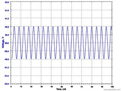
Passive wheel speed sensor waveform
In the case of passive sensors, the signal, and resulting waveform is sinusoidal, in which both the amplitude and frequency change with increasing speed. In this waveform, the “peaks” and “valleys” represent alternating high/low energy states within the broader signal.
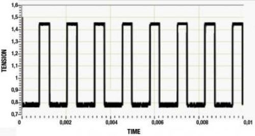
Active wheel speed sensor waveform
With active wheel speed sensors, the amplitude (height) of the waveform does not change; only the frequency of the waveform changes with increasing speed. In this waveform, the square “peaks” and “troughs” represent “ON and “OFF” signals.
It should be noted that the above examples are intended for illustrative purposes only. The actual amplitude and frequency of the waveform that is displayed on the oscilloscope during testing depends on the rotational speed of the wheel, the number and separation of the teeth on the reluctor ring, and the width of the air gap between the sensing magnet and the reluctor ring. Note that the overall condition of both the sensor and the reluctor ring, and the integrity of the associated wiring harness are also critical factors to consider when diagnosing wheel speed sensor issues.
Testing wheel speed sensors is no more difficult than testing other similar sensors. However, it must be borne in mind that since wheel speed sensors are critical to safe vehicle operation, it is important to have access to all pertinent technical information such as resistance values, which MUST be verified for both accuracy and relevance to the affected vehicle. Moreover, to ensure a successful repair, you MUST have access to the following-
As with all diagnostic procedures, you can save a lot of time and hassle by performing a proper visual inspection of the sensor. Despite the harsh conditions that wheel speed sensors operate under due to their location, many issues with these sensors can often be resolved without spending much time and energy so by following the preliminary checks outlined below, you can often find and fix the problem relatively easily regardless of the type of sensors involved.
Get as much information from your customer as you can
This is especially important if you are dealing with an intermittent issue, and the information you get is sometimes invaluable as a diagnostic aid. For instance, ask the customer if the ABS or other warning lights only come on when driving on rough roads, or only in wet weather. If warning lights come on or brake performance is affected on rough or uneven road surfaces, suspect bad connections in one or more connectors. If issues occur only in wet or rainy conditions, suspect short circuits caused by water entering connectors.
Check wheel bearings
Excessive free play in wheel bearings can have dramatic effects on the operation of wheel speed sensors, since the play in the bearing can move the reluctor ring away from the sensing magnet. This is especially true in cases where the reluctor ring or magnetic encoder in located inside the bearing. In these cases, the best course of action is to replace the affected wheel bearing(s) before continuing the diagnostic procedure.
Check tyre sizes and inflation
If the problem appeared immediately, or soon after a tyre replacement, verify that all the tyres on the vehicle are of the same type/ diameter, and that all are inflated to the correct pressure. Since variations in wheel diameters cause differences in wheel rotation speeds, the ECU will interpret this as defects in one or more wheel speed sensors.
Inspect the wheel speed sensors and wiring for damage
Place the vehicle on jack stands, and remove wheel(s) as required to make it easier to inspect the affected sensor(s). Remove the affected sensor, and inspect it for any signs of physical damage such as impact damage, cracks, corrosion, or anything else that looks out of the ordinary. If any such damage is found, replace the sensor as a matter of course. Also, inspect all associated wiring that is immediately accessible for evidence of chafing, rubbing, or anything else that might have caused a short or open circuit. Repair or replace wiring as required.
Inspect the reluctor ring
Since most reluctor rings are located on CV-joints, it often happens that CV-joints with incorrect reluctor rings are fitted as replacements. To verify that this is (or is not) the case on the affected vehicle, it may be necessary to remove the drive shafts to physically compare the reluctor rings, since any differences will be recognised by the ECU and/or the ABS control module as defects in the sensors.
However, if no CV-joints were replaced, inspect the reluctor ring on the affected sensor for signs of damage, but bear in mind that even slight damage to just one tooth can cause the sensor to generate false or erratic signals. Also, inspect the reluctor ring for signs of dirt or other debris between the teeth, as this will also cause false, implausible, erratic, or sometimes, no signal to be generated. Remove all debris on the reluctor ring as required.
Test the sensor’s internal resistance
Bear in mind that there is no single resistance value that is valid for all wheel speed sensors on all applications. Compare the obtained reading with the manufacturer’s specified value, and replace the sensor if the obtained reading deviates from the specified value by more than one, or at most, two percent.
Check that the sensor actually works
Disconnect the affected sensor, and connect the red lead of a multimeter to the signal wire in the connector, and the black lead to a suitable ground. If the sensor works, the multimeter will display a voltage when the wheel is spun by hand. Bear in mind however, that this will only tell you that the sensor is working- it will not tell you how well the sensor works, or if works all of the time.
NOTE: While this test can be performed on passive sensors, it does not really work on active sensors. The best way to test an active sensor is to connect the leads of an oscilloscope to the signal wire and a suitable ground.
Test all wiring
While testing procedures vary between manufacturers, a generic diagnostic procedure will generally occur along the following lines-
If the above checks did not resolve the problem, it becomes necessary to test-drive the vehicle with a scan tool (that incorporates an oscilloscope) connected to the date link connector. This is the most reliable way of detecting issues such as an intermittent loss of communication that are commonly caused by vibration while the vehicle is in motion. These types of issues can generally not be detected by spinning a vehicle’s wheels by hand. Here is what to look out for-
